Four Ways to Compute an Inverse FFT Using the Forward FFT Algorithm
If you need to compute inverse fast Fourier transforms (inverse FFTs) but you only have forward FFT software (or forward FFT FPGA cores) available to you, below are four ways to solve your problem.
Preliminaries
To define what we're thinking about here, an N-point forward FFT and an N-point inverse FFT are described by:
$$ \qquad \qquad \qquad = {1 \over N} \sum_{m=0}^{N-1} [X_{real}(m) + jX_{imag}(m)]e^{j2\pi mn/N} \tag{2}$$
Inverse FFT Method# 1
The first method of computing inverse FFTs using the forward FFT was proposed as a "novel" technique in 1988 [1]. That method is shown in Figure 1.
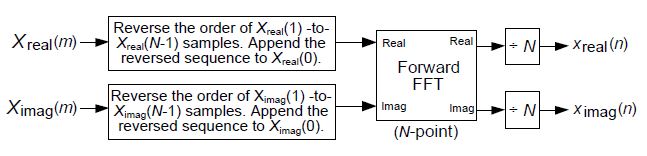
Figure 1: Method# 1 for computing the inverse FFT
using forward FFT software.
Inverse FFT Method# 2
The second method of computing inverse FFTs using the forward FFT, similar to Method#1, is shown in Figure 2(a). This Method# 2 has an advantage over Method# 1 when the input $ X(m) $ spectral samples are conjugate symmetric. In that case, shown in Figure 2(b), only one data flipping operation is needed because the output of the forward FFT will be real-only.
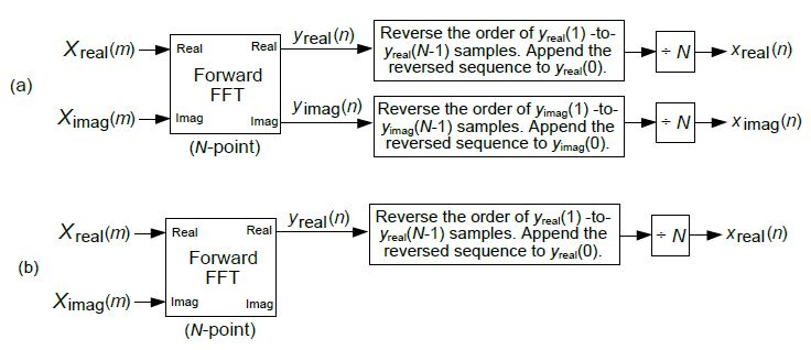
Figure 2: Method# 2 Processing flow: (a) standard Method# 2;
(b) Method# 2 when X(m) samples are conjugate
symmetric.
The next two inverse FFT methods are of interest because they avoid the data reversals necessary in Method# 1 and Method# 2.
Inverse FFT Method# 3
The third method of computing inverse FFTs using the forward FFT, by way of data swapping, is shown in Figure 3.
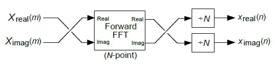
Figure 3: Method# 3 for computing the inverse FFT
using forward FFT software.
Inverse FFT Method# 4
The fourth method of computing inverse FFTs using the forward FFT, by way of complex conjugation, is shown in Figure 4.
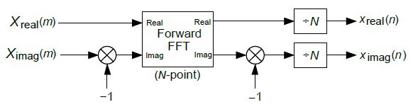
Figure 4: Method# 4 for computing the inverse FFT
using forward FFT software.
References
[1] Duhamel P., el al, "On Computing the Inverse DFT", IEEE Trans.
on Acoustics, Speech, and Signal Processing, Vol. 36, No. 2,
Feb. 1988.
- Comments
- Write a Comment Select to add a comment
Hi, Rick.
I don't understand how the structure "Forward FFT" actually works. according to the blog, the IFFT of X_real(m) is x_real(n), but x_real(n) is not the true real part of x(n).though x(n)=x_real(n)+ j* x_imag(n),both x_real(n) and x_imag(n) can be complex, i.e.,they are not real commonly. So waht does the output of "Forward FFT" mean?
thank you,
luka
Hello luka.
The "Forward FFT" block in my blog is the standard, traditional, N-point radix-2 FFT algorithm covered in all the DSP textbooks. Note, in most standard FFT tutorials the author shows the input to an FFT to be a real-only sequence (x-real(n) only), but the standard FFT can also process a complex-valued input sequence (x_real(n)+j*x_imag(n)).
In my blog sequences x_real(n), x_imag(n), y_real(n), and y_imag(n) are all real-valued sequences.
The sequences 'x_real(n)+j*x_imag(n)' and 'y_real(n)+jy_imag(n)' are complex-valued.
Let me know if you have any further questions.
Hi Rick. thanks for your reply!
I guess my understanding of the relationship between x(n) and X(m) as reflected in the flowchart is not clear. Using Method 1 as an example, does the flowchart consider the IFFT of X-real(m) to be x-real(n)?
At the beginning of the blog, my understanding of the IFFT formula is that you can write x(n) as “[IFFT of X-real(m)]+j*[IFFT of X-imag(m)]”. But since x-real(n) is real and IFFT of X-real(m) is generally complex, the two are generally not equal. The same is true for x-imag(n).
So I'm still not sure how to recognize “Forward FFT”. Can I understand that the inputs and outputs are both complex numbers, but the real part of the inputs and outputs are not related to each other in the normal DFT way?
Thanks again for your reply.
Hello luka.
In my blog's Eq. (1), the standard DFT equation that I
labeled as "FFT", the input x(n) sequence can be a
complex-valued. Now in the vast majority of practical
DFT applications the x(n) sequence is real-valued. In
those applications the x(n) sequence is
x(n) = x_real(n) + jx_imag(n) with x_imag(n) being a
sequence of all zero-valued samples, thus x(n) is a
real-valued sequence.
In the vast majority of practical DFT applications the
DFT of a real-valued time-domain x(n) input will be the
complex frequency-domain sequence X(m) = X_real(m)+jX_imag(m).
(My Eq. (1)). If you e-mailed me a complex X(m) DFT output
sequence I could compute your original x(n) input sequence by
computing the IDFT of your complex X(m). I *CANNOT* compute
your original x(n) input sequence by computing the IDFT of
just the real part of your complex X(m) sequence.
We *CANNOT* write
x(n) as “[IFFT of X_real(m)]+j*[IFFT of X_imag(m)].”
My Eq. (2) says we write x(n) as the IFFT of the
[X_real(m)+jX_imag(m)] complex frequency-domain sequence.
luka, your Comment's last paragraph is essentially true.
x(n) inputs to a DFT can be complex, but in practice (using
real-world input signals from sensors or an antenna) x(n) is
almost always real-valued. The X(m) outputs of a DFT of a real-valued
x(n) are almost always (99.9999% of the time) complex-valued sequences.
I say "99.9999% of the time" because a highly unusual x(n)
sequence, where the second to the last x(n) samples are
symmetrical, will have a DFT output that is real only.
For example the DFT of x(n) = [5,1,2,3,2,1] is the real
only X(m) = [14+j0,1+j0,5+j0,4+j0,5+j0,1+j0].
To post reply to a comment, click on the 'reply' button attached to each comment. To post a new comment (not a reply to a comment) check out the 'Write a Comment' tab at the top of the comments.
Please login (on the right) if you already have an account on this platform.
Otherwise, please use this form to register (free) an join one of the largest online community for Electrical/Embedded/DSP/FPGA/ML engineers: