DSPRelated.com
Blogs

The Swiss Army Knife of Digital Networks

Rick LyonsJune 13, 201612 comments

This blog describes a general discrete-signal network that appears, in various forms, inside so many DSP applications. 

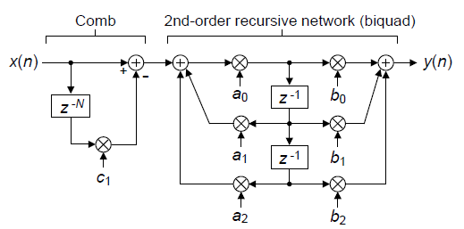
Figure 1 shows how the network's structure has the distinct look of a digital filter—a comb filter followed by a 2nd-order recursive network. However, I do not call this useful network a filter because its capabilities extend far beyond simple filtering. Through a series of examples I've illustrated the fundamental strength of this Swiss Army Knife of digital networks and its ability to be reconfigured to perform an astounding number of useful functions based on the values of its seven control coefficients.

This article is available in PDF format for easy printing

Figure 1. General discrete-signal processing network.

The Figure 1 network has a transfer function of

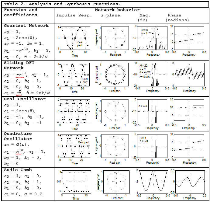
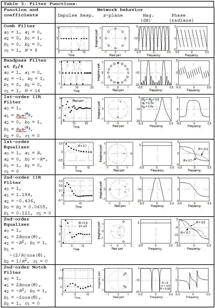
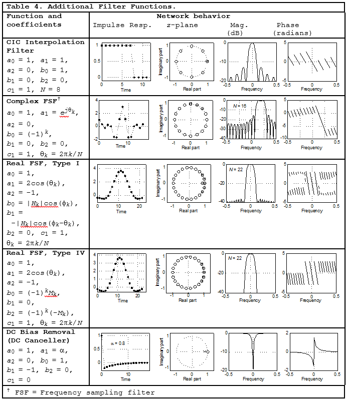
$$ H(z) = \frac{Y(z)}{X(z)} = (1-c_1z^{-N})\frac{b_0 + b_1z^{-1} + b_2z^{-2}}{1/a_0 - a_1z^{-1} - a_2z^{-2}} \tag{1}$$

The tables in this blog list various signal processing functions performed by the network based on the $ a_n,\ b_n\ and\ c_1 $ coefficients. Variable $ N $ is the order of the comb filter. Included in the tables are depictions of the network's impulse response, z-plane pole/zero locations, as well as frequency-domain magnitude and phase responses. The frequency axes in those tables is normalized such that a value of 0.5 represents a frequency of $ f_s / 2 $ where $ f_s $ is the sample rate in Hz.

To keep this blog manageable in size, detailed explanations of the network Functions in the following tables are contained in the downloadable PDF file associated with this blog.

[NOTE FROM AUTHOR LYONS (Oct. 2018): The downloadable PDF file has been updated since this blog’s original posting in June 2016.]


[ - ]
Comment by Tim WescottJune 13, 2016
Rick:

I don't see any provisions for integrator anti-windup.

:)
[ - ]
Comment by MartinMcCormickJune 15, 2016
Making the integrator slightly leaky would be fine for the moving averager and other a_1 = 1 configurations. Shouldn't be much of a difference, just a slight decay in moving average window. At least the comb is before the integrator!
[ - ]
Comment by aserJuly 3, 2016
Pole-zero diagrams are useful.
May be better to explain the equaliser as an allpass filter.
[ - ]
Comment by SerhiiRybkaSeptember 16, 2021

Dear Rick,

Question regarding Table 4, Real FSF Type IV:

Could you please advise from your experience what maximum value can take N-comb filter order at practical implementation?

Best regards, Serhii Rybka

[ - ]
Comment by Rick LyonsSeptember 17, 2021

Hello SerhilRybka.

Keeping in mind that the order of the comb subfilter, used in a Real FSF Type IV lowpass digital filter, determines how many memory locations are required I don't know of any limit on the comb subfilter's order.

[ - ]
Comment by SerhiiRybkaSeptember 18, 2021

Dear Rick,

Thanks a lot for your reply. I have another question on this topic - why in the books you are not considering bandpass filter based on real FSF Type IV?

Best regards, Serhii

[ - ]
Comment by Rick LyonsSeptember 18, 2021
Hello SerhilRybka.

When I wrote about real FSF Type IV in the 3rd edition of my "Understanding DSP" book I concentrated on lowpass filters. But in my book's Table 7-3 I mentioned that such filters could be used for bandpass filtering.

[ - ]
Comment by Rick LyonsSeptember 19, 2021
Hello SerhilRybka.

If you're designing an FSF Type IV digital filter for some actual filtering implementation send me an e-mail at: R.Lyons@ieee.org

[ - ]
Comment by leoeltipoApril 11, 2025

Hi Rick,

First of all, thanks for this article. If you start typing "the swiss army knife..." in my google bar it will autocomplete haha. Have used this so many times.

I have a (maybe silly) couple of questions.

First, it's a bit hard for me to understand the difference between Goertzel and the DFT bin. I understand that decimating the Goertzel filter output by N gives the same output as the corresponding DFT bin, but does that mean that the Goertzel is better estimate if you don't decimate? (say I need a running estimate of a particular bin).

Second, what is the difference between a Goertzel at theta and having a complex mixer at -theta and then an integrator at DC. Just asking as that may allow me to dynamically modify the frequency without having to worry about updating the complex coefficients. Are these 2 structures comparable? May the second one be more unstable?

Thanks a lot. As usual, your contributions are just amazing!

Leo
 

[ - ]
Comment by Rick LyonsApril 11, 2025

Hello Leo.

If you need to compute a new complex-valued DFT bin output sample upon the arrival of each new x(n) input sample, then I suggest you use an algorithm that's called the "Sliding DFT". I like to think of the Sliding DFT as a "real-time DFT bin calculator."

The original version of the Sliding DFT described over 20 years ago was computationally efficient and useful, but not guaranteed stable. I've seen at least a half dozen papers describing different methods of implementing a guaranteed-stable Sliding DFT, but those algorithms increase the necessary computations per input sample.

[By the way, the Goertzel algorithm while not "real-time" is indeed guaranteed-stable.]

Years ago I developed what I believe is, so far, the most computationally efficient guaranteed-stable Sliding DFT. That efficient algorithm, described in a paper titled "Improvements to the Sliding Discrete Fourier Transform Algorithm", can be found at:

(PDF) Improvements to the Sliding Discrete Fourier Transform Algorithm

or

Improvements to the Sliding Discrete Fourier Transform Algorithm [Tips & Tricks] | IEEE Journals & Magazine | IEEE Xplore

As for your second question, a good question indeed, I'm afraid to try to answer it off the top of my head. I'm sure I thought about that "complex downconversion and DC integration" scheme many years ago. But I don't have any happy memories concerning it and I've don't recall seeing anyone using that scheme in a Sliding DFT-type algorithm. So I'm guessing that scheme is suboptimal in some way. However, with MATLAB or OCTAVE you can experiment with that "complex downconversion and DC integration" scheme to see how well you can make it work. (Keep in mind, no matter what algorithm you use, when you change a network's coefficients you have to process at least N input samples before you can compute your first correct DFT bin output sample.)

I'm sorry I couldn't be of more help regarding your second question.

Good Luck.


[ - ]
Comment by leoeltipoApril 14, 2025

Hi Rick,

Thanks a lot, this is all very valuable info! I've just downloaded that DSP Tips and Tricks article. Will go through it I agree I was thinking I guess sliding DFT should be better for "real-time".

Back to the down-conversion thing, I always think of this as an alternative as implementing a DDS block with Time-domain multiplexing of different frequencies is not too expensive and then the "filter" is always at DC, fixed coefficients.

Anyway thanks a lot for the reply and all the information!

Leo

[ - ]
Comment by Rick LyonsApril 15, 2025

Hi Leo.

I can see that you are a civilized and friendly guy.

Regarding that "improved sliding DFT" paper that I and my co-author wrote, there's a little trick that makes the network even more computationally efficient. In Figure 3(a) of the paper I have a "comb stage", followed by a "complex feedforward" stage, followed by a "real resonator" stage. Because all the stages are linear time-invariant networks we can interchange their order of execution. The "trick" is to interchange the feedforward and the real resonator stages. That is, implement the "comb stage", followed by the "real resonator" stage, followed by the "complex feedforward" stage.

That beneficial rearrangement of the stages is something that occurred to me *AFTER* the paper was published. Shame on me for not thinking of that rearrangement *BEFORE* the paper was published.

Leo, I've written this reply after having two Kentucky bourbons. I felt like telling you the "story" behind the creation of that improved sliding DFT paper. But, mercifully, I won't bore you to death with that story. Lucky you.

Take Care,

[-Rick-]

To post reply to a comment, click on the 'reply' button attached to each comment. To post a new comment (not a reply to a comment) check out the 'Write a Comment' tab at the top of the comments.

Please login (on the right) if you already have an account on this platform.

Otherwise, please use this form to register (free) an join one of the largest online community for Electrical/Embedded/DSP/FPGA/ML engineers: