


Direct Form II
The signal flow graph for the Direct-Form-II (DF-II) realization of the second-order IIR filter section is shown in Fig.9.2.
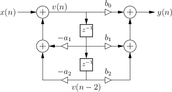
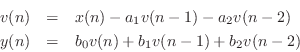
The difference equation for the second-order DF-II structure can be written as
which can be interpreted as a two-pole filter followed in series by a two-zero filter. This contrasts with the DF-I structure of the previous section (diagrammed in Fig.9.1) in which the two-zero FIR section precedes the two-pole recursive section in series. Since LTI filters in series commute (§6.7), we may reverse this ordering and implement an all-pole filter followed by an FIR filter in series. In other words, the zeros may come first, followed by the poles, without changing the transfer function. When this is done, it is easy to see that the delay elements in the two filter sections contain the same numbers (see Fig.5.1). As a result, a single delay line can be shared between the all-pole and all-zero (FIR) sections. This new combined structure is called ``direct form II'' [60, p. 153-155]. The second-order case is shown in Fig.9.2. It specifies exactly the same digital filter as shown in Fig.9.1 in the case of infinite-precision numerical computations.
In summary, the DF-II structure has the following properties:
- It can be regarded as a two-pole filter section followed by a two-zero
filter section.
- It is canonical with respect to delay. This happens because
delay elements associated with the two-pole and two-zero sections are
shared.
- In fixed-point arithmetic, overflow can
occur at the delay-line input (output
of the leftmost summer in Fig.9.2), unlike in the DF-I
implementation.
- As with all direct-form filter structures, the poles
and zeros are sensitive to round-off errors in the coefficients
 and
and  , especially for high transfer-function orders. Lower
sensitivity is obtained using series low-order sections (e.g., second
order), or by using ladder or lattice filter structures
[86].
, especially for high transfer-function orders. Lower
sensitivity is obtained using series low-order sections (e.g., second
order), or by using ladder or lattice filter structures
[86].
More about Potential Internal Overflow of DF-II
Since the poles come first in the DF-II realization of an IIR filter,
the signal entering the state delay-line (see Fig.9.2) typically
requires a larger dynamic range than the output signal ![]() . In
other words, it is common for the feedback portion of a DF-II IIR
filter to provide a large signal boost which is then
compensated by attenuation in the feedforward portion (the
zeros). As a result, if the input dynamic range is to remain
unrestricted, the two delay elements may need to be implemented with
high-order guard bits to accommodate an extended dynamic range.
If the number of bits in the delay elements is doubled (which still
does not guarantee impossibility of internal overflow), the benefit of
halving the number of delays relative to the DF-I structure is
approximately canceled. In other words, the DF-II structure, which is
canonical with respect to delay, may require just as much or more
memory as the DF-I structure, even though the DF-I uses twice as many
addressable delay elements for the filter state memory.
. In
other words, it is common for the feedback portion of a DF-II IIR
filter to provide a large signal boost which is then
compensated by attenuation in the feedforward portion (the
zeros). As a result, if the input dynamic range is to remain
unrestricted, the two delay elements may need to be implemented with
high-order guard bits to accommodate an extended dynamic range.
If the number of bits in the delay elements is doubled (which still
does not guarantee impossibility of internal overflow), the benefit of
halving the number of delays relative to the DF-I structure is
approximately canceled. In other words, the DF-II structure, which is
canonical with respect to delay, may require just as much or more
memory as the DF-I structure, even though the DF-I uses twice as many
addressable delay elements for the filter state memory.
Next Section:
Transposed Direct-Forms
Previous Section:
Direct-Form I


