


Generate a signal with linearly increasing Bandwidth
Hi all,
How can i generate a signal with linearly increasing bandwidth over time? (It means i want to calculate STFT and expect the spectrum to expend with each iteration of STFT.)
For example: Chirp signal has a linearly increasing frequency over time.
Thanks,
Deepak
Unless I am misunderstanding your question, you're going to need a linearly increasing sample rate to get a linearly increasing bandwidth which I don't see how you would do that.
First
I think you should try to think in terms of a digital system since you
want to code this up in Matlab. In a digital system, your STFT is
really just going to be an FFT. You don't want your sample rate to
change inside
an FFT frame, so the best you can do is a piecewise increasing
bandwidth which increases from one FFT frame to the next. Based on this
"It means i want to calculate STFT and expect the spectrum to expend
with each iteration of STFT." I think that is what you want.
Say you start with sample rate fs, an FFT size of N, and you want your bandwidth to increase at a rate of M. I think what you need to do to accomplish this is after N samples, compute an N-point FFT. Then interpolate your sample rate to fs*M,
get M*N samples, and compute an N*M-point FFT. Then interpolate the
sample rate to fs*2*M, get 2*M*N samples, and compute an 2*N*M-point
FFT, and so on. In this example I am interpolating the sample rate after
every FFT frame because it sounds like that is what you're asking for
in your question, but I think your code is going to max out your
CPU pretty fast doing that in real-time. I think you'll want to interpolate your
sample rate every X FFT frames.
I think the best way to accomplish the sample rate conversions in Matlab would be to generate a signal with the highest sample rate you're going to need, and think of it as
starting with a highly decimated sample rate and each time you
"increase" your bandwidth you are decimating this starting sample rate
by slightly less. I think that is more likely to work than actually trying to interpolate the sample rate with each bandwidth increase. Either way your max bandwidth will certainly be bounded, what that bound is depends on your system.
Does this sound like what you were looking for?
Hi Jjamison,
I don't want to change the sampling rate. I want to sample the signal at the good enough rate so it can cover upto highest frequency of the signal.
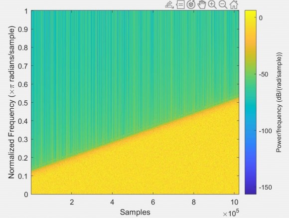
For example, after using a variable cutoff frequency filter, which is changed over a frame, i get below spectrogram. I have kept the sampling rate constant and used Gaussian white noise as input.

I like the variable sample rate idea from the other poster. That said... if you can handle a piece-wise steps in BW, I recommend using a multi-sine whose frequency steps within your region of excitation are chosen to give you starting and ending points at complete cycles. This would allow you to concatenate the sequences without discontinuities. Then, you could just generate output blocks for each BW and - after stitching them together - have the sequence that you need.
I wrote an m-file that stepped from 30-300Hz to 30-3000Hz in 1Hz steps each a 0.1s interval driven with a 10KHz sample rate. The spectrogram looks like this:
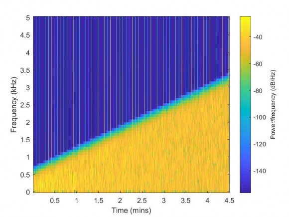
If the code is of interest, I can post it.
Hi djmaguire,
Specrogram looks nice. Please share the code.
Thanks,
Deepak
Hi Deepak,
The variable sample rate idea of the other poster - at least the way that I interpreted it - was to have random noise at various sample rates (and so, bandwidths) that you upsample to your fixed rate. It seemed reasonable.
Here you go on code. Sorry for the lack of comments. I'm a bit rushed these days and I put this together as a mix of old code and new. I had to do it lightning fast.
The frequency bounds are not exact. Remember that the prime directive is that the sinusoids of the multisine segment exist as complete cycles so that the segments can be concatenated without discontinuity.
Best,
Dan
N=1000; FreqLow=30; FreqHighStart=300; FreqHighStop=3000; Fs=10000;
clear F D y q;
start=1;
for fstep=FreqHighStart:FreqHighStop
Flow=FreqLow; Fhi=fstep;
t=[0:1/Fs:(N-1)/Fs];
F=[0:N-1]/N*Fs;
Nlo=round(Flow/Fs*N);
Nhi=round(Fhi/Fs*N);
F=F(Nlo:Nhi);
F=F';
D=ones(length(F),1);
D(:,2)=F;
D(:,3)=randn(length(F),1)*180;
t=t';
y=zeros(length(t),1);
[component, j]=size(D);
for i=1:component
ph=2.0*ones(length(t),1)*D(i,3)*pi/180.0;
angle=2.0*pi*D(i,2)*t;
y=y+D(i,1)*sin(angle+ph);
end
y=y/max(abs(y));
if start==1
q=y';
start=0;
else
q=[q y'];
end
end
One other thought, also, for someone willing to throw hardware at this problem...
Connect a random noise generator to the input of a high-order switch-capacitor lowpass filter. Use a second pulse/function generator or computer-controlled square wave generator as the clock input to the filter. ...and record the output at your desired sample rate.
Crude, maybe. ...but easy enough.
Something like the MAX291.
Hello Dan,
Thank you very much for providing the code. I was able to run the code successfully. Got below spectrogram:
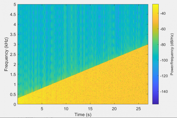
I also wrote my own code on the same idea given by you. I have maintained continuity by using a single time vector for entire signal duration and later picking up time instants suitable for particular frame. By doing so we don't to check frequencies for complete cycles within frame duration and can obtain exact frequency bounds.
I notice the difference of background power. With your code, it's constant, while with my code, it's increasing with Bandwidth. In my code, signal power is increasing with increase in bandwidth. I am not sure if that can cause this.
Here is the code:
Fs = 1e4;% Input sample rate
frameLength = 1000;
%Variable bandwidth
variableBandwidth = 300:10:3000;
numFrames = length(variableBandwidth);
Tend = frameLength*numFrames*(1/Fs);
expT = (0:1/Fs:Tend-(1/Fs))';
% Initial Signal frequency
freq = 30:10:290;
sig = zeros(numFrames*frameLength, 1);
%Generate varying bandwidth signal
for Index=1:numFrames
tempIndex = (Index-1)*frameLength+1;
%Initial Signal
tempSig = sin(2*pi*expT(tempIndex:Index*frameLength)*freq);
sig(tempIndex:Index*frameLength) = sum(tempSig, 2);
%Signals to add at each frame
addSig = sin(2*pi*expT(tempIndex:Index*frameLength)*variableBandwidth(1:Index));
%Final Signal
sig(tempIndex:Index*frameLength) = sig(tempIndex:Index*frameLength)+ sum(addSig, 2);
% sig(tempIndex:Index*frameLength) = sig(tempIndex:Index*frameLength)/max(abs(sig(tempIndex:Index*frameLength)));
end
sig = sig/max(abs(sig));
spectrogram(sig, 1024, 24, 5000, Fs, 'yaxis')
Please have a look at my code if you have time.
Thanks Dan,
Deepak
Hi Deepak,
You are welcome. Glad to read of your good result. I will take a look at the code today.
Best regards,
Dan
Hi Deepak,
The issue looks to be that you are normalizing your signal magnitude at the end of your creation of your final additive block. Please keep in mind that the summation of the sinusoids will have varying peak magnitudes/crest factors - especially so with zero relative phase between components.
I am normalizing my gain within each block. You are creating the entire signal and then normalizing at the end. Because of that, here is a time-domain comparison of our two signal (yours=left, mine=right):
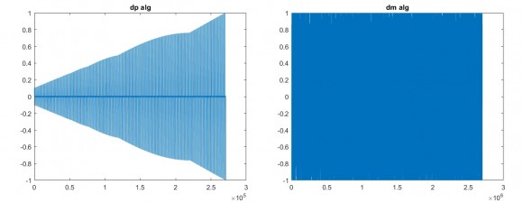
I believe that what you are seeing is an artifact of the spectrogram calculation as it relates to the varying magnitude of your signal. I believe that if you normalize your signal component magnitudes within your for() loop, you should see better consistency between our code in the frequency domain.
That said... I do realize that my code unnecessarily recalculates components. That is because my multi-sine code was originally used for calculating excitation sequences for active noise and vibration control systems. I just threw it in a for() loop for your application. Quick for me but wasteful in terms of computations!
Best,
Dan
Hi Dan,
I wanted to keep the signal that way, as i mentioned previously that signal power is increasing with each frame. The reason for doing so is that i want to add a constant power signal at each frame.
About normalizing over frames, If we normalize over each frame and try to maintain a constant envelop, will it not cause the individual frequency components power to reduce over each frame?
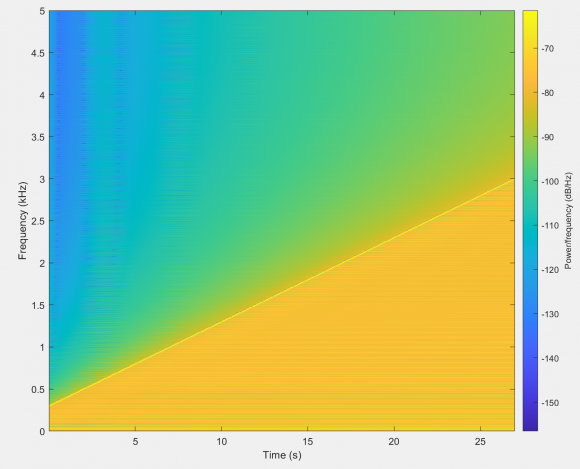
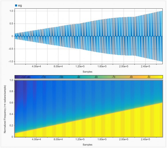
I think i was using wrong configurations for spectrogram. After using signal analyzer, i get below spectrogram.
Thank you very much for your help and Input on my code Dan. Appreciate it.
Thanks,
Deepak
Hi Deepak,
Yes, sorry. I had forgotten about that constraint. ...and yes to the parameters of the spectrogram. I had noticed the sensitivity before I got off on my power tangent.
...and yes, also, to a minimization of power. In my original single block code, I had a section that randomized relative phase to minimize crest factor. I pulled that out because it seemed confusing. But, that would help to address the decreasing power while maintaining uniform magnitude.
Again, my application was a bit different. Glad to help.
Best,
Dan

Hi,
A simple way is to use multiple chirp generators. YOu can control the bandwidth with the "boundary" chirps and also can add chirps in between these two. YOu may also distort-blur-low pass (could be a little hard?) chirp outputs if you dont want to see linear lines in the spectrum.
or addding segments of gaussian white noises filtered with changing band pass filters could be tried also. You may check this.
Hi Omersayli,
I am currently working on this but not getting desired results. What i have noticed is that because of using white gaussian noise as input, with increase bandwidth of filter, fluctuations also increase in bandwidth. Is there any way to counter these fluctuations?
Thanks for your help.
Hi Omersayli,
I tried that method. I used cumsum function in matlab to add samples over time.
For example if i have a vector X = [1 2 3 4 5 6];
then cumsum gives ans:[1 3 6 10 15 21];
I used it over a chirp signal which means i am creating a new chirp signal at every sample and adding it with previous chirps.
But the problem with this method is that i end up with a signal of unknown Bandwidth.
I think that chirp signal generated at time instant 0 will define the bandwidth as it will have the highest frequency component at all time instants. So frequency_of_first_chirp(T)-frequency_of_first_chirp(0) should give the bandwidth. But seems like it's not working.
What do you think? What needs to be done?
Can you check this

What coding environment are you using?
Hi Michael,
I am using MATLAB.
Matlab does have a CHIRP function.
Yes, but it has increasing frequency. I want to generate a signal with increasing bandwidth.

you can do reverse engineering of ifft. start with zeros vector and insert any bandwidth as non zeros, do ifft and you got the signal generated. (do fft and you get it back to prove it).
Hi Kaz,
That's an interesting idea. But the problem i see with frequency approach is the IFFT points. Constructed signal accuracy will be restricted by the IFFT points. If i don't want to have more than 1000 samples for one frame, then this small number of samples may not be enough to construct signal properly with higher bandwidths.
To over come this, jjamison has suggested varying sampling rates for each frame(considering each frame has a fixed time duration).
Thanks for your suggestion Kaz.
Thanks,
Deepak


