


Hello,
I've been playing around with #Convolution Reverb for the past few months in regards to a Master's Thesis, and recently noticed some strange results when utilizing *irregular impulse response's (IR's).
*Note: By "irregular", we mean IR's which don't adhere to the standard definition of an IR (ex. drop in amplitude by 60 db).
I believe I have an idea of what's going on, but I was hoping someone could confirm my results.
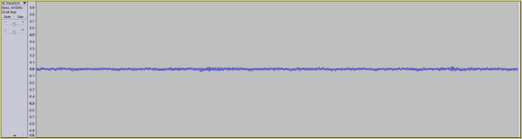
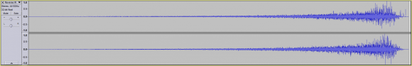
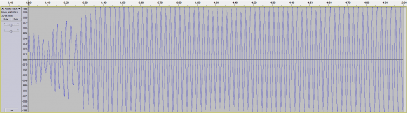
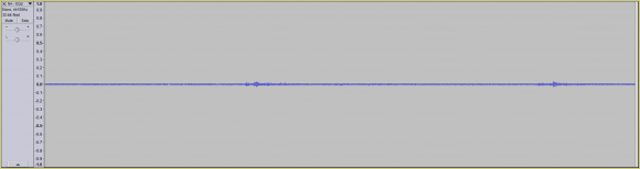
Assuming we wish to reverberate the following waveform:
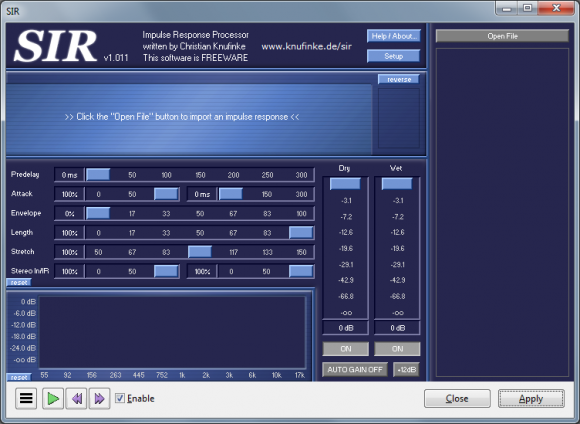
...using the following two IR's:

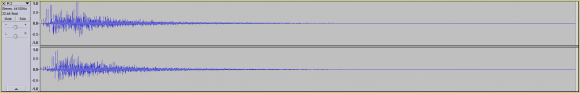
...we notice the following result (after reverberating the waveform with the first IR):

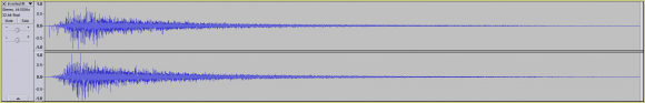
...and the following result (after reverberating the waveform with the second IR):
So far nothing seems out of the ordinary.
Even if we were to use the same IR multiple times, we notice the same sort of general waveform progression. Namely that with every subsequent reverberation, the reverberated waveform grows larger.
However, if we were to use the same waveform in different orientations, we notice something different.
Assuming we used the same IR, but in the following orientations:
1. Forwards (normal phase):

2. Inverted (phase inverted):
3. Reversed (normal phase but reversed):
4. Reversed and Inverted (phased inverted and reversed):
...we notice some odd results.
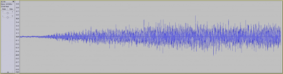
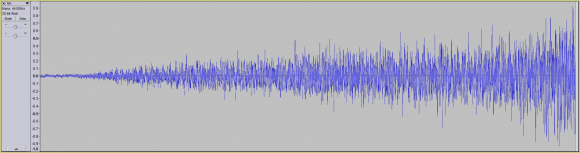
For example, reverberating the following signal:

...with the first IR (normal phase), results in the following waveform:
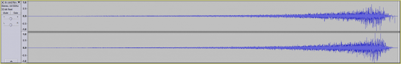
Even when using the second IR (inverted phase), we notice no major issues:
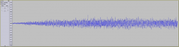
However, when using the third IR (normal phase but reversed), we begin to notice some odd behavior:
Though the waveform has grown in size (towards the rear), if we look very closely, we can actually see a slight amount of what looks like waveform phase cancellation:
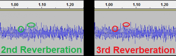
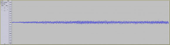
Though the phase cancellation is small, it's when we use the 4th IR (inverted phase and reversed), that we see the biggest amount of what looks like phase cancellation:
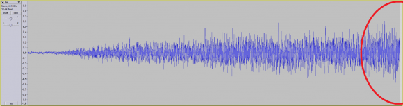
Notice how the rear of the waveform has massively dropped in amplitude (highlighted in red), compared to the previously reverberated waveform.
This result leaves me with the following questions:
1. Am I actually witnessing a partial phase cancellation (when using the 3rd and 4th IR)?
...and if so:
2. Why am I seeing a phase cancellation only after the using the 3rd and 4th IR's?
...and lastly:
2. How would I go about maximizing the waveform phase cancellation?
For example, if we were to dramatically increase the amplitude of the 3rd and 4th IR (in comparison to the 1st and 2nd IR), would we end up with even more phase cancellation?
Thank you,
Nelson
Convolution is all about phase-cancellation. What the convolution actually does is take your original signal and create N copies of it (for an N sample impulse response). Then it shifts every copy n by n samples and multiplies it by the value of the nth sample of the impulse response. All these shifted and amplified versions of your original are then added together - depending on the sample values of your impulse response there will of course be a lot of phase cancellation going on. That's what convolution is all about.
A 180 degree phase shift of an entire impulse response will change nothing except the phse of the output - which will also be shifted by 180 degrees.
A reversed impulse response will have the same frequency response only inverted phase (now, I didn't check that against the formulas - its just my feeling). But in your case the frequency response is so long that it is alot longer than the time/frequency resolution of your ear - and that is why you will also hear a temporal reversal - which is self-evident: If you reverse a sound of a gun-shot, you will here increasing reverb followed by a sharp crack.
Hello ,
Thank you for the clear and concise explanation.
I had a quick follow-up question I was hoping you could answer.
If as you say, through the use of convolution reverb we encounter phase cancellation.
Would that mean that deriving the IR responsible for generating a reverberated signal is impossible?
In other words, if I have a dry signal and I run it through a convolution reverb plugin using a specific IR, resulting in a reverberated / wet signal.
Would it be possible to mathematically generate the IR (100% accurate) which was used to generate the reverberated / wet signal?
Thank you,
Nelson

I'm a bit out of my area of expertise here, but I believe that it is not only possible, but a done thing to find the impulse response of a system given a "dry" signal that you have selected.
The 100% accurate part is harder, but I believe it can be done if you're willing to put up with calculating a sufficiently long impulse response.
Finding the impulse response of a system given an arbitrary "dry" signal is not generally possible: basically, the prototype signal has to have sufficient information in it to do the job; if the original signal is not rich enough in content (for instance, a single-tone sine wave is probably the worst possible choice), then extracting an accurate room model would be the equivalent of dividing zero by zero and getting something useful.
Hello Tim,
Thank you very much for your input.
I was wondering if you could clarify something in regards to using a single-tone sine wave.
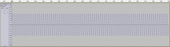
Assuming our dry signal is a 40 Hz sine wave:
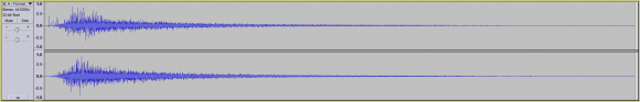
...and our IR is the following waveform:

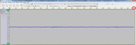
Are you stating that if we were to run our dry signal through a convolution reverb plugin / software using our IR, resulting in the following waveform:
...that someone couldn't derive the IR, if all they were given was the dry signal and the reverberated / resultant signal?
If so, mathematically or even conceptually, why would that be?
Thank you very much for all your help,
Nelson
So, first, we're running afoul of the correct definition of a sine wave. In the mathematically pure sense, a 40Hz sine wave has been going at 40Hz since forever, and will continue on forever. So what you're showing is the reverberation for a gated 40Hz sine wave -- one that starts up at some time, and continues on forever.
A "forever" 40Hz sine wave in would give you a 40Hz sine wave out, similar to the right side of your output plot. That would only tell you what's happening at 40Hz, and nowhere else. You'd get information at one data point where you need to get information at tens of thousands (assuming a room reverberation time in the seconds, and a sampling rate in the tens of kHz).
In theory, with perfect, noise-free measuring instruments, all the information you need is in that gated sine wave, because the gating creates information across the entire spectrum. In practice, the energy of that gated sine wave is concentrated around 40Hz -- the only useful information about the room response is in the first 15 cycles or so of the response, the rest is just redundant.
So if your "mathematically or conceptually" definition encompasses perfect noise-free instruments, then yes, maybe you could extract the room response from the response to the gated sine wave. In practice, there would be so little energy in the original prototype signal that at frequencies away from 40Hz information in the return would be swamped by noise, and therefor would be useless.
Hello Tim,
Though I'm not certain I completely understand your explanation (due to my lack of DSP knowledge), I think I understand the basic gist of your explanation.
In regards to the following statement:
"So if your "mathematically or conceptually" definition encompasses perfect noise-free instruments, then yes, maybe you could extract the room response from the response to the gated sine wave. In practice, there would be so little energy in the original prototype signal that at frequencies away from 40Hz information in the return would be swamped by noise, and therefor would be useless."
Can I assume what you mean is that, theoretically in a perfect scenario (which does not exist in reality), we could deduce the IR used to add reverb to a dry sine wave signal (ex. at 40 Hz)?
However, realistically speaking, if you or I were given a dry signal and a wet signal (which had gone through some convolution reverb processing), but nothing else. It would be impossible to accurately derive the IR responsible for generating the wet signal?
My apologies if I misunderstood you, but my thesis chair is claiming that no matter the situation, deriving the IR from a wet signal is mathematically trivial. That said, he's more of a mathematician / Computer Science professor rather than a DSP professor.
That being said, at least in his discretized examples of waveforms, everything seems to make sense. In other words, when using a simplified discrete waveform, I don't see anything that would make me think that deriving an IR would be impossible or at the very least, very difficult.
That being said, he and I could both be wrong.
Thank you,
Nelson
Yes and no.
Theoretically, in a perfect scenario, you could deduce the room response with THAT wet signal generated by THAT dry signal (the gated 40Hz tone).
Realistically, given an arbitrary dry signal and the wet signal that results from it, you cannot determine the room response. The problem is that to go from the wet and dry signal to the room response, you need to perform a deconvolution. Deconvolution, at some level, requires doing a matrix inversion (if you're lucky they're two diagonal matrices, but it's still a matrix inversion). The dry signal determines the eigenvalues of the matrix to be inverted -- if you have zero eigenvalues, or even a wide spread of eigenvalues, then you can't do the deconvolution.
I based my "theoretically in a perfect scenario" statement on the fact that the 40Hz gated tone works out to a matrix with all non-zero eigenvalues -- but the ratio between the largest and smallest is going to be several orders of magnitude.
The problem is the arbitrary dry signal. You correct this by choosing a dry signal that is well-conditioned. You use a chirp or a pseudo-random sequence that's really white or a series of impulses spaced farther apart than the room's reverberation time or some such. Any of these will have flat spectra in the frequency domain -- and the spectra in the frequency domain is the eigenvalues of one of the matrices that you need to invert for the purposes of deconvolution.
(Note that I haven't done system identification on rooms. Motors and other mechanical systems, yes, definitely, I have. Communications channels, yes, I've done that too once or twice. But not rooms -- so I can't give you a good reason why you should use one model over the other.)
A reversed impulse response will have the same frequency response only inverted phase (now, I didn't check that against the formulas - its just my feeling).
You are correct. Time-reversing the impulse response of a filter doesn't change the magnitude response in the frequency domain, it just (rather dramatically) changes the phase response.

Hello nelsona. I bet someone here can help you, but you'll have to help us do that by providing more information. What the mathematical nature of this thing you call "Convolution Reverb"? What do you mean by "strange results?"
Your words:
"... IR's which don't adhere to the standard definition
of an IR (ex. drop in amplitude by 60 db)."
are mysterious, to me at least. What do they mean exactly? The definition of an "impulse response" is well known and straightforward. How can you have an "impulse response" that is not an impulse response? Where did that strange "60 dB" value come from?
I wonder if the other guys here know what is meant by the phrase "reverberate the following waveform." You wrote:
"...use the same waveform in different orientations,..."
Can you tell us what the phrase "different orientations" means? I'm not an audio signal processing guy so perhaps my above questions are simple-minded and should be ignored.
By the way, if X(m) is the DFT spectrum of some x(n) time sequence, a time reversal (i.e., straight reversal NOT "circular reversal") of x(n) will produce a time sequence whose DFT magnitudes do not change from X(m)'s magnitudes but whose phases are shifted by 180 degrees from X(m)'s phases.
Hello Rick,
My sincere apologies for being a bit vague, as my background in DSP is quite lacking.
- As for what I mean by convolution reverb, I'd say that I'm referring to the effect of running a dry signal through a convolution reverb plugin / software (which is itself a mathematical approximation of the effect of convolution reverb):
- As for what I meant by "non-standard impulse response"; in my particular example I meant something like the reversed IR and reversed + inverted IR which rather than decay by 60 db's, actually have an attack which grows by 60 db's (as one example).
- The 60 db value comes from the "reverberation time" also known as RT60.
From Wikipedia: https://en.wikipedia.org/wiki/Reverberation
"The time it takes for a signal to drop by 60 dB is the reverberation time.
RT60 is the time required for reflections of a direct sound to decay 60 dB.
Reverberation time is frequently stated as a single value, if measured
as a wide band signal (20 Hz to 20 kHz), however, being frequency
dependent, it can be more precisely described in terms of frequency
bands (one octave, 1/3 octave, 1/6 octave, etc.). Being frequency
dependent, the reverberation time measured in narrow bands will differ
depending on the frequency band being measured."
- By reverberate, I meant the effect of running a dry signal through some piece of software which approximate the effects of convolution reverb.
The resultant waveform is the reverberated waveform.
In other words, reverb has been applied to the dry signal, resulting in a wet / reverberated signal.
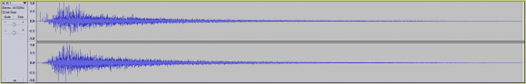
- As for "different orientations", what I meant was using an IR such as the following:

...in different orientations.
So if the image above pertains to my default IR, if I reverse the IR:

...we have a new orientation.
If I then flip the phase of the reversed IR:

...we have yet another orientation of the same waveform.
Thank you,
Nelson
By "irregular", we mean IR's which don't adhere to the standard definition of an IR (ex. drop in amplitude by 60 db).
Huh? I've never heard this term. Is it specific to reverberation, or to your thesis project, or what? The standard definition of impulse response just says it's what the system does -- do you mean the normal impulse response of some canonical filter, like a low pass? Amplitude drop relative to what? In the time domain? In the frequency domain?
What do you mean by "phase inverted?" To this long-time circuit designer and fan of antique radios, "phase inversion" means to multiply everything by -1. It can't be that simple.
And finally -- is it possible to get the scales on your graphs readable? If not, could you state in the text what the scales are?
Hello Tim,
- By "irregular", I meant something like an IR which had an inverted reverberation time (as one example).
For example, the following IR:

...has a reverberation time (aka RT60) of almost 2 seconds.
However, if I were to reverse the IR, resulting in the following IR:

...we'd have an attack time of nearly 2 seconds, followed by a steep drop.
- I also may have misspoke when using the term "reverberation", by reverberation I meant the effect of running a dry signal through a piece of software which approximates the effect of convolution reverb being applied to that dry signal using a specific IR.
- By phase inverted, I meant taking a waveform:

...and flipping it on its vertical axis:
- As for the scales:
Each waveform image is 2 seconds in length (see ):
As for the vertical scale of -1 to 1 (see green), I believe the values range from 0 db to -90 db.
Thanks,
Nelson
Hello Tim,
Quick question, would you be able to send me an email at the following email address: nelsonasemail@gmail.com
...as I'd like to quickly run my Master's Thesis by you, to see if it's at all feasible (both I and my Committee Chair don't currently believe it is).
If you don't have time or the interest, no worries as I completely understand.
That being said, I wanted to thank you (and everyone else on these forums), for all your help and insight in helping me understand the basic concepts necessary to complete my Master's Thesis.
Thank you,
Nelson
Before I do that, could you post the abstract of your thesis in a new thread, with a title along the lines of "Is This Work Feasible?". Maybe include the core concept that you're trying to implement that's different from other room model extraction techniques.
I do this for several reasons: one, I prefer to do this sort of free help publicly, in hopes that it'll lead to work; two, I'm not an expert in this room reverberation stuff and I think there are people here who are (and thus will be of more help, or at least higher-quality help), and three, it sounds time consuming and (unfortunately) time isn't something I have a lot of right now.
Hello Tim,
I'm a little nervous about divulging the thesis of my Master's as I feel I'm onto something that's never been published before (though I could be wrong).
That said, I'm not planning on patenting anything, but would like to be able to at least be the first to publish my work (as it could greatly help me career-wise, which for the past 6 months hasn't been going that well).
That said, I completely understand where you're coming from in regards to me posting my thesis on the forum.
Nelson
OK, that sounds wacky.
Given a specific dry signal that has holes in the spectrum, then you could design an impulse response that was rich in energy where the dry signal has holes. Conversely, given a specific impulse response you could design a specific dry signal with holes where the impulse response has lots of energy.
I'm not sure if that's enough to make things work, though.
Hello Tim,
So just to be certain, if I had the following audio signal:

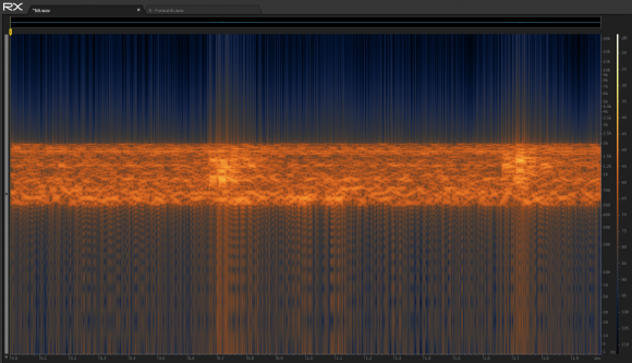
...which looks like the following in a Spectrogram:
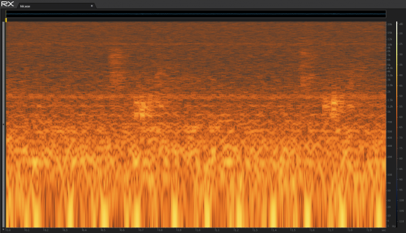
...and I was using the following IR (to apply reverb to my dry signal):

...which looks like the following in a Spectrogram:
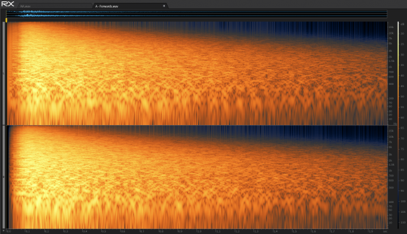
...that if I removed let's say everything except for the mid-range in my dry signal (between 500 Hz and 2 Khz), resulting in the following waveform:
...with the following Spectrogram output:

...and performed the opposite on my IR (removing everything in between 500 Hz and 2 Khz), resulting in the following IR waveform:

...with the following Spectrogram output:
...that it would be very difficult if not impossible for someone to determine the IR used to add reverb to the dry signal (if all they had was the dry and wet signal)?
If so, would you happen to know what this phenomena is called?
Or at least mathematically or conceptually, why it should work?
Thank you very much for all your help,
Nelson
Oh damn. Now that I see the spectrograms I realize that if you ran that dry signal through that filter, the answer would be zero. Don't believe me, though -- try it.
Hello Tim,
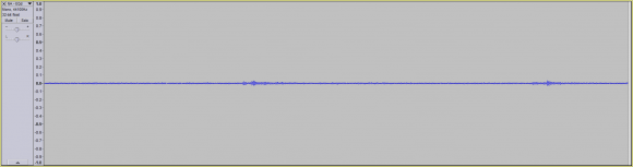
I did try it and took the following dry signal (removing all frequencies outside of 500 Hz - 2 Khz):
...and used the following IR (removing all frequencies between 500 Hz - 2 Khz):
...on that signal, resulting in the following wet / reverberated signal:

Note: There was a change in the dry signal (after using the IR to add reverb), but the change was small / hardly significant.
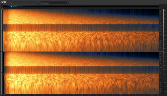
When examining the Spectrogram for the wet signal, we see the following:

...which is only slightly different than the Spectrogram for the dry signal:
Question: Can I assume from the results above, that your suggestion didn't work, and that I should instead look to some other manner of preventing the IR from being deconvolved?
Thank you,
Nelson


