


Dear signal processing enthusiasts:
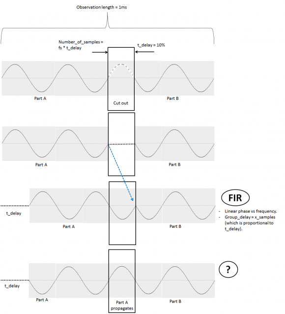
- I am forced to cut off a part of a multi-frequency signal, creating a "gap" as shown in the figure. (only one frequency to simplify illustration).
- If I inject part A of the signal into a FIR which has linear phase vs frequency, and set the FIR to have a group_delay proportional to the gap length, the output's phase doesn't change, and hence the stitched signal has a phase jump.
- I am looking for a filter that would let part A propagate through, to the point where its phase matches part B's phase. Does such a filter exist?
The question in different words:
how can i phase-shift a multi-frequency discrete signal in time-domain? The phase shift should be linear with frequency.
Here is my chain of thoughts:
- I imagine that, if I inject a sin wave into a transmission-line, its phase when it exits will depend on the length of that transmission-line. If i want a different phase value, I would adjust the transmission-line length.
- If the signal has multiple frequencies, each frequency component will then have a different phase shift in a linear manner.
- If I were to do this in frequency domain, I would multiply the spectrum with a phase shift as in: exp(j.w.t_delay), where w is the frequency axis and t_delay would be the time delay value as to simulate the transmission-line's length.
- I am however unable to do it in frequency-domain because I am only able to observe the signal for a limited amount of time = limited number of samples = worst resolution for the frequency axis w. (frequency resolution = 1/observation_time).
- Any phase correction will only work for the signal frequencies which are on the w "grid", and not any off-grid ones.
- I therefore started thinking of how can one do such a thing in time-domain? wouldn't such a system or filter have both characteristics of liner phase vs frequency and linear phase vs time? Does such a filter/system exist?
Interpolation and extrapolation of signals are two of the 3 reasons for which linear filters were invented (see the seminal work by Wiener: "Extrapolation, Interpolation and Smoothing of Time Series"). However, if you have a finite number of sines then the best filter to use is an AR filter (with a finite number of poles), not an FIR one.
However, the optimal extrapolation filter depends on the frequencies and amplitudes of the sines in the your signal. To see why, think of a single sine. If you know its period then you could extrapolate it by copying forward (with proper interpolation if the period is not an integral number of samples).
So, what you need to do is to perform LPC analysis (of size appropriate to the number of sines in your signal) on the portion where you have signal, and switch over to the corresponding synthesis filter during the gap. For reference see the frame loss concealment algorithms that are integral to all of modern speech codecs.
Alternatively, you might try any of the eigenspace methods, such as Pisarenko or MUSIC, and then synthesize by hand. If you had a single sine I would definitely do a Pisarenko!
Unfortunately, using extrapolation you are not guaranteed to perfectly match with the signal after the gap, since small estimation errors accumulate. So, if you don't have to be perfect real-time (i.e., you can introduce a little delay in order to see some of the signal after the gap) a better method is to solve the LPC equations both forward and backward. I have done this many times and it works well (if you can afford the delay).
Y(J)S
Hi,
Thank you very much for the interesting explanation. It looks like LPC analysis will work for me. The eigenspace methods, such as Pisarenko or MUSIC you mentioned do not - as it seems - report-back the various spectrum components' amplitudes and phases. Amplitudes and phases are important to the application (remote sensing) because they provide info on the objects being sensed.
I will start playing with LPC in Matlab and see how it works.
Your comment puzzles me.
All of the methods estimate the spectral components in one way or another, however, the eigenspace methods directly find the frequencies, while LPC methods calculate LPC coefficients (or some linear combination of them such as PARCOR, LSP, etc). From the LPC coefficients you have to build the polynomial and find its roots to obtain the frequencies, which is an indirect process and can lead to numeric and/or computational complexity difficulties for high-order polynomials. Pisarenko directly outputs the complex exponentials.
You didn't mention the real-time issue - are you delay constrained? Using LPC based on the past only can lead to (hopefully small) discontinuities when the signal returns, which (depending on application) can be unimportant, annoying, or problematic. If you must work without delay and these continuities give you problems, then rather than returning directly to the signal try fade-in/fade-out. If you can afford some delay (or are working off-line) then LPC interpolation rather than extrapolation is the way to go (although not well-known).
Y(J)S

This is very much the same issue as when one is trying to build an "endless loop" of a sound record out of a limited amount of data. The issue there is "how long will the loop record be - exactly?" in order to avoid those abrupt changes.
I did research on this some years ago. Our first criterion was that the result had to "sound good". We built a memory whose temporal length was determined by a variable sample rate on the "input". Then we played back the output of the memory. So, initially, it was a simple delay. Then we would loop back the output into the input and stop sampling altogether in order to observe the result of the sample in memory and the endless loop performance.
One thing we learned from this was that keeping the length of the loop fixed and starting with new samples would make a difference. Some samples sounded great and others had obvious transients. So we would push the "sample now" button time after time until we had a good result. Bottom line, the same length (so likely the same gap) can be dealt with by judicious selection of the location of the gap. AND, if you have no control over the position and length of the gap then the likelihood is that you will be unhappy. That's because we had more "bad" samples than "good" samples. AND, this was after adjusting the loop length!
Of course, all this was empirical and your question is more theoretical. It raises the questions:
1) do you have control over the gap length and location?
2) what, exactly, is the objective here? See below about "phase".
I would recommend that you set "phase" thinking aside and concentrate on delay.
Suppose that the signal is truly periodic. If you know the period and if you know the gap length, you can calculate the amount of time that's needed to match the signals, i.e. remove the gap. If the signal is not periodic then it's tougher. Yet, consider this:
If you can take the FFT of a segment of the signal (conceptually at least) and be able to maintain the necessary fidelity then the frequency sample rate is the reciprocal of the period or window. In other words, you can select a period that may be "good enough".
A good example is the sum of 1Hz and PiHz. This is not a periodic signal. But, you may be able to decide how much time is necessary to be "close enough" for your purposes.
A simple approach to the general problem here is to match both the sample value and the slopes at the stitch point - within some ranges. Beyond that it will depend on what you need for you particular application.
Hi Fred,
I enjoyed reading your reply! Thank you for taking the time. The infinite loop thing must have been interesting.
To answer your questions:
- I do have control over the gap length, but not its location in the observation.
- The signal is not periodic. It has frequencies ranging from a few hertz to 5MHz. I draw one frequency for illustration only. The objective: spectral analysis of the data, in a way that maintains frequency component amplitudes and phases for remote sensing. This is why I am considering the FFT. The signal has a limited observation time of 1ms.
I guess I am going to try the memory solution and see how the results will look like, then perhaps look for a spectrum estimation method that - like the FFT - that maintains spectral components' amplitudes and phases.
OK. If the observation time is limited to 1ms then the frequency resolution will be limited to 1/1ms=1kHz. That rather leaves out "from a few Hz".
There are a couple of ways to think of this limitation:
1) the window length of 1ms has a Fourier Transform that's sinx/x in frequency and has a main lobe width of around 1kHz. That's a nice physical limitation view I should think.
Well, in fact, the zeros of the sinx/x will be 1kHz apart.
2) Using a Discrete Fourier Transform, with a temporal window of 1ms, the frequency sample rate will be 1kHz no matter the temporal sample rate. Here's an example:
Window: 1ms
Sample rate: 1.024MHz
Number of samples:1,024
Sample rate of 1.024MHz divided by 1,024 samples (in time AND in frequency) yields 1kHz per frequency sample.
Now, this may be why you want a longer sample and are motivated to stitch samples together. The "gap" thing is a bit puzzling though. More info on that?

My short answer is that you can't chop off part of a signal then stitch back without phase break...unless it is made up of few preknown discrete sinusoids.
A gap means "no information" and there is no way to get it back but you can either suppress the phase discontinuity by windowing or create false samples by extrapolation or ignore the section if irrelevant.
Thank you.. I guess I will start looking at extrapolation.

Tudelft_Res,
I guess the answer depends on the type of signal and what you are using the signal for. For example, if your purpose were spectral analysis, you could treat the segments before and after the break as two signals and window each one before taking the FFT.
regards,
Neil
Hi Neil,
Thank you for your reply. The purpose is indeed spectral analysis.
- If I take the FFT of each segment alone, I lose resolution because of having less samples (observation-time).
- If I window each part and take the FFT of the whole, the peaks in the spectrum - when zoom'd in on - have funny double-peaks, instead the standard sync function peak.
Is there a way to take separate FFTs of both segments and some how combine the FFT results to increase resolution?
Tudelft_Res,
To get more frequency resolution, you could zero-pad the segments **after** windowing. For example, if one segment were length 1500, you could window it, then zero-pad it to length 2048 or 4096, etc.
Also, you could average the two FFT's. If the two segments are x1 and x2, then
h1= freqz(x1,0,Nfft,fs); % fft over 0 to fs/2
h2= freqz(x2,0,Nfft,fs);
hsq= [(abs(h1)).^2 + (abs(h2)).^2]/2
H= 10*log10(hsq);
regards,
Neil


