


Hi guys!
I'm on to a new task and try to implement a FIR filter (transposed form) after a CIC as a compensation filter. So far, so good, the simulation runs fine and the filter seems to work. Sending a 1 through it gives me all the single coefficients as pulse response and its suitable for even and odd numbers of coefficients alike.
The only problem I have is the output amplitude, because it seems that the input and output amplitude are off by a factor of 4. Can I just multiply my coefficients by 4 to reach the same output amplitude?
Here my VHDL implementation and my testbench

That should work, yes.
Hi, heck the filter gain! Your coeffs scaling is probably problem.
Also, before going to HW, a simple and easy MATLAB (or similar!) exercise will eliminate potential problems. There is an excellent topic related to sinc filters (which you designing) in MATLAB help (I believe in HDL coder tool box).
good luck!
fd

"output amplitude" resulting from what INPUT??
How can the "input amplitude" be off?? It is what it is, no?
"Same output amplitude" as what?
Sorry to be so picky but all these are important in answering your question.

Yes, multiplying your coefficients by a factor will increase the gain by this factor, but I would recommend that you try to understand what is happening so you can learn from it.
If the impulse response test you did causes the output to faithfully reproduce the coefficients, then there is clearly nothing wrong with the FIR, but rather that the design of your coefficients is inappropriate. However, it is not clear from your post whether simulation predicted this gain error. If not, then your VHDL might be implicated.

you should consider power gain rather than amplitude gain and then at some frequency e.g. dc gain or your passband gain. I assume you mean you are not getting any unity gain. Then try to identify what you are after.

"Can I just multiply my coefficients by 4 to reach the same output amplitude?"
Yes. In fact, that is how I design most of my FIR filters... Design the shape, and then normalize to the gain you want it to have.
Sorry, I thought that would be clear from my simulation and testbench.
So I've made a compensator filter via an octave script, which gave me 33 coefficients for my FIR, that are multiplied by 2^15 and later in the fpga divided by this value.
For testing, I give in a jump from 0 to 7FFFFFFF and the output value of the filter is kind of what I expect. If I give in a pulse, I'm getting all my coefficients out of the output, so this should behave like a FIR. In my case, I reduce the amplitude of my input signal that I need for a lockin and PID.
Now I've multiplied my coefficients from this script by 2, which are as follows:
3,36E-04
-4,88E-04
6,41E-04
-1,10E-03
1,71E-03
-2,75E-03
4,15E-03
-6,35E-03
9,46E-03
-1,43E-02
2,15E-02
-3,34E-02
5,34E-02
-9,11E-02
1,71E-01
-3,72E-01
1,00E+00
-3,72E-01
1,71E-01
-9,11E-02
5,34E-02
-3,34E-02
2,15E-02
-1,43E-02
9,46E-03
-6,35E-03
4,15E-03
-2,75E-03
1,71E-03
-1,10E-03
6,41E-04
-4,88E-04
3,36E-04
and implemented them into my FIR (see cCoeff constants).
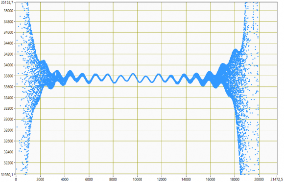
It seems to work as I can see in my test with a constant amplitude and frequency sweep on the real FPGA. In the picture you see several sweeps and I guess it's obvious where I deactivated the compensator via a mux.
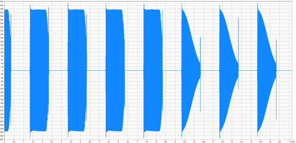
But if I look closely into my test, I still have a change in amplitude that looks like a sine, it's not really a straight line as it is in my simulation with octave.
Is this a problem of my FIR implementation in VHDL, is this normal for a FIR compensator filter or is my script a bit wrong and I'm getting coefficients that are not suitable for my needs?
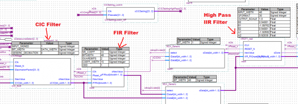
This is how it's implemented on the FPGA side, just if someone is curious about it
the sum of your FIR coeffs is 15763 yet you divide by 2^15. That is a gain of 0.48
you should scale them so that sum is 2^15
THAT was the problem, thanks a lot! :)


