


Arbitrary Resampling issue : 30.72 MHz to 20 MHz
 Started by 6 years ago●20 replies●latest reply 6 years ago●499 views
Hi,
I have two signals. Signal A, sampling rate 30.72 MHz and signal B, sampling rate 20 MHz. Their center frequency is same though.
Now assuming a simultaneous transmission of both he signals and ignoring co-channel interference, how can I receive both of them using single RF front end simultaneously.
Previously I perform a similar task where Signal A's sampling rate was 4 MHz, so I sampled at 20 MHz for signal B and down sampled by 5 to get 4 MHz signal A.
But for the present case, if I first sample at 30.72, then in order to obtain signal B, I have to resample by 125/192, which I believe is a a costly operation!
What could be other approaches ?
Regards
Sumit

125/192 may not be that costly, you may need a large lookup table for coeffs but few multipliers. You can run an accumumulator as +192 modulo 125 then address the LUT cyclically picking up a set of coeffs to produce an output sample.
Are you talking about polyphase resampler.
yes, 125 polyphases in LUT then you just calculate those samples that are not going to be discarded.

Does the sampling rate at the receiver need to match the sampling rate at the transmitter?
No, provided that I can upsample/downsample it finally to 30.72 and 20 MHz.
30.72 MHz signal is coming from LTE and 20 MHz signal is coming from WiFi. Center freq is same.
So at the receiver, I plan to first sample at 30.72 and then resample.
But I can go for higher sampling rate also if that helps !
Until I ran into some compelling reason to do otherwise, I would sample it at whatever was convenient, bring it down to baseband at a sampling rate that is appropriate for the bandwidth of the signal, do my processing, then regenerate the baseband signals separately at their required sampling rates.
But -- without getting into the fine detail, I wouldn't know if one of those compelling reasons I mention exists.
Ok I might not have explained properly :)
but here is a diagram which can explain better.
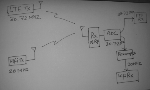
Your original text says that the sampling rates are 30.72MHz and 20MHz, but your drawing seems to indicate that you're talking about carriers -- except that those are absurd carrier frequencies for those services.
Are you talking about the chip rates for spread spectrum?
My apologies, I should have used standard notations.
So, 30.72 MHz is the sampling rate of LTE and 20 MHz is sampling rate of 802.11a.
ADC performs sampling at 30.72 MHz and resampler block resamples at 125/192 to derieve 20 MHz from 30.72 MHz.
I don't know what is the target for this processing, but if it is an FPGA I would do this resampling task in multiple steps.
125/192 = 5/4 x 5/4 x 5/12 = 5/6 x 5/4 x 5/8
You need 5 phases for each step which saves a lot of memory.
You have to find the right ordering so that:
- you never go below 20MHz
- you optimize the number of multipliers
When you up-convert (5/4 filters in this example) you must be able to compute more than one output sample per input sample (1 or 2 output sample per input in this example).
When you down-convert, you must be able to compute at most 1 output sample per input.
The second solution (5/6.5/4.5/8) seems to be the best solution at first glance (only 1 up-conversion), but it needs confirmation.
Olivier
Olivier,
You can do it in 3 stages. But for fpga one design is easier and quicker than 3 designs I believe.
The one design approach is the well known fractional rate converter. A 125 polyphase each with 8 coeffs for example will only need 8 multipliers. It will need 125*8*bitwidth memory and one accumulator.
The original filter itself will have 125 x 8 coeffs and should not only cut off closest interpolation image at .5/125 but also at .5/192 to avoid aliasing at decimation. This filter is then split into 125 polyphases.
The accumulator should run as +192 modulo 125 to point to each polyphase
Such implementation is efficient because we don't compute the 191 samples that will be discarded but only one sample per 192.
Kaz
Kaz,
It's true that if you take your filter example even a single multiplier is enough, running at 246.76MHz.
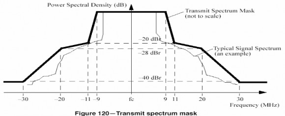
I just had a look to the Channel filter specifications and it is not very constrained:
Hi,
Depending on your hardware constraints and filter response requirements, one efficient structure for this is the so-called transposed farrow structure. It typically makes sense if you can achieve your filtering specifications with a low-order polynomial frequency response (linear or up to 3rd order like cubic spline). The polynomial coefficients are calculated online from the data (exactly like you would do for a standard linear interpolator), but in a decimating context.
If you can't achieve the specifications with a low-order polynomial, you can always split the problem in two: use the transposed farrow to decimate by an 'integer ratio' of the overall desired ratio, and follow up with a better integer decimator (easy to implement). Here you could use the farrow to decimate by 1/4 * 192/125 = 0.38, followed up with a standard decimate by 4.
Here is a good reference:
Gretzteam,
Thanks for the link but I am lost. It talks about three types of rate conversion:
(1) integer
(2) fractional
(3) irrational
I have never heard of (3) and where/how to implement it. Any comments appreciated
Kaz
Hi,
The way I think of it is as follow:
(1) integer: ...
(2) fractional: any number that can be represented as a fraction of integers...like the case here.
(3) irrational: sub-case of fractional, where the ratio is slowly changing over time. For example an audio sample rate converter might be converting from 48k to 44.1k (160/147), but if the data source/sink are derived from independent clock source, that ratio is changing and has to be tracked. Typically a PLL is used to recover the ratio and provide the fractional resampling instant.
This highlights a powerful feature of polynomial filters: they can be used to do (3) with the same hardware as (2) since the coefficients are calculated on the fly from the data and the provided fractional interval (ratio).
In the case of the OP, the fractional instant could be calculated by integrating the ratio 125/192 since it is known and fixed (although this is an assumption I'm making). Alternatively, a PLL could be generating the 'irrational' ratio to integrate, while the filter would stay the same.
Hope this helps,
Dave
Thanks Dave. That seems interesting but I think it is not the way we work in FPGAs. All Clocks have to be tied up together or prevented from drift. setup/hold Timing have to be managed and buffering could get out of control otherwise.
However I have met a case of video streams coming through serdes where clock was recovered from data and buffering was then done to maintain streaming. There was fractional upsampling far away near the DAC and I used a feedback arrangement controlling the buffer output rate based on rate converter as master such that I always upsampled to same output rate irrespective of changing input rate.
Kaz
Hi Kaz,
This has nothing to do with FPGA or ASIC implementation. The problem of irrational rate conversion happens all the time. The case you highlighted is one of those. If your input rate is slowly varying, and your output rate is constant, then the upsampling ratio is constantly changing and adapting to the irrational ratio between the two clocks. Sometimes you go a bit too fast, sometimes a bit too slow. You essentially implemented a digital PLL monitoring buffer indexes to track the ratio.
Hi Dave,
Yes I agree it happens in any platform. I managed that with feedback arrangement and never thought there is an alternative. This feedback controlled the input rate. I am not clear how the polynomial filter approach will control input rate side but admittedly haven't read details of that link paper yet.
Hi,
Imagine a case where you cannot control the input rate. Say the data comes from an ADC running at a fixed rate from its own oscillator. In such a case all you can do is to filter the data to calculate the sample value you need at your sampling instant.
A standard linear interpolate (draw a line between two points and calculate a new value on that line) does that. That paper is essentially about doing the same thing in a decimating context.
Thanks, that reminds me of a qpsk/16QAM demodulator clock recovery with free running ADC oscillator. To hit the peaks/troughs of symbols, either the adc clock phase has to be shifted (outside fpga) through a feedback or it is let free running sampling data anywhere and fpga signal has to be recreated from incoming adc signal. The fpga has to get high peaks/troughs at symbol rate by interpolation, and occasionally adding or discarding samples. I think this was Farrow resampler and may be we are on same path.


