


Synchronising output of Farrow resampler with PPS signal
 Started by 5 years ago●16 replies●latest reply 5 years ago●482 views
Dear all,
I am working on a project that has basically two requirements:
1) Fractional resampling of the input signal (fractions can be in the order of 41,001/50000)
2) One output sample is coincident with PPS signal.
Well, I could satisfy the first requirement by using a first order Farrow resampler. My plan for the second part was to manipulate the delay in Farrow resampler. So, if the last sample is not going to be coincident with PPS, then I add a tiny extra delay to the Farrow sampling time, to make it coincident with PPS.
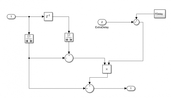
This strategy does not work very well. Almost 90% of the time Simulink gives me timing errors. To resolve the errors, I put the rate transition block of Matlab on the specific sample times. Then, I have to reduce the time step to a value that can be divided by input and output sample times. Such tiny time steps have one drawback of super long simulation time. Even with that, my output samples are not synced with PPS. Here is my simplified schematic of modified Farrow filter (this is a Matlab generated first order Farrow, I just try to add my ExtraDelay with FDelay).
Can you please advise if such approach like this is appropriate to synchronise the output of Farrow resampler with an external signal (e.g. PPS).
All comments are greatly appreciated.
Morteza

Hi,
From where do you get delay value(FD)?

You are using a 1st order farrow, which is nothing more than a linear interpolation.
From your diagram, I see a link from a scaled (by the left interpolator coefficient) copy of the input to a summation in the bottom branch, that I don't understand.
I also don't understand the multiplier in the in the top branch of the bottom summation. How is the extra delay applied with a multiplier?
David
Hi David ,
This to me looks like this simulink fractional delay example(end of page).
Hi Kaz & David,
Thanks a lot for the link. This looks exactly what I needed. Your sharp insights into the problem are greatly appreciated.
Why Kaz's post does not have a beer button?
All the best,
Morteza
Hi Morteza,
I don't drink apart from water.
Dear Kaz,
Thanks for the link.
I expect from a fractional delay block to delay the input samples by a fraction of the sample times. However, both input and output seem to coincide all the times. Please see this code.
clc; clear all; close all;
sine = dsp.SineWave('Frequency',50,'SamplesPerFrame',150);
x  = sine();
delay=1.5;
farrowFracDelay = dsp.VariableFractionalDelay( ...
    'InterpolationMethod','Farrow','MaximumDelay',1025)
y = farrowFracDelay(x,delay);


fracDelay = dsp.VariableFractionalDelay;
y2 = fracDelay(x,delay);
figure(1)
subplot(211)
plot(x)
hold on;
plot(y)
plot(y2)
subplot(212)
stem(x)
hold on;
stem(y)
stem(y2)
xlim([0 50])
legend('x','y','y2')
The code above produces the following figure.
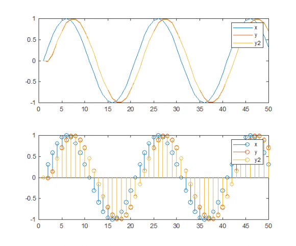
It seems the block just translates the requested delay into some extra phase delay, rather shifting the sample times.
Please advise if I've got something wrong.
Best regards,
Morteza
I wouldn't worry about those matlab functions you used.
All you need is first order FD (as first stage).
here is what fd function should do under the bonnet:
x = cos(2*pi*(0:99)*.037);
d = .1;
y = x;
for i = 2:length(y)
y(i) = (x(i-1) - x(i))*d + x(i);
end
plot(x,'*-');hold;
plot(y,'*-r');
I expect d to be 0 to 1 (or -.5 to .5)
Hi @Kaz,
Thanks for the quick reply.
I found something interesting. We just need to shift the output signal by the amount of the delay in the fractional filter. In the other words, the fractional delay, interpolates the original signal (sampled at \(t\)) at the times that are \(t+\Delta\).
So, we may amend the code by shifting the output the samples for proper alignment.
stem(x,'o-');hold;
stem([0:99]+d,y,'*-r');
xlim([0 30])
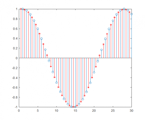
Is this interpretation correct?
Kind regards,
Morteza
Salam Morteza,
Yes for first statement. FD creates new samples at any point you choose between two samples. so at d of .01 it creates new samples at value of 1/100 as if adc has delayed its sampling phase by 1/100. and a -.01 for advance.
Your second statement is not needed because you want to delay by a fraction. so why shift back and forth and would an adc do that?
all you need to think of is adc samples (x) signal and that is what you got. but you want to digitally recreate (x) as if it was sampled into new phase.
The terms delay/advance are relative to a given sample. what matters to the "eye" is the trend of signal rather than location of samples relative to original.
the final issue is the case when delay/advance gets more than 1. you drop/create extra new sample to match the rates.
The error "d" (TED = Timing Error Detector) can be used to force adc clock into required phase and this is the classic analogue solution. It just requires shifting left/right of zero error and does not require Farrow. for digital option adc is left free (democratic solution) and the Farrow is tasked with sample recreation so it needs to get actual value of d, not just the zeroing.
Your main task should be to define how to get TED then what order Farrow to use. TED is one module. Farrow is second and a third is needed; negative feedback loop filter plus scaling challenge. Or if it helps use forward processing without negative feedback.
Kaz

Hello Morteza,
I've designed several of these in Simulink, it is my preferred tool. I'll help you with the design if you will agree to fully document the method here in a white paper along with Matlab design source code and example Simulink code. It is something I'll never have time to do.
To start with we need much more information.
What is your incoming sample rate? Is your incoming signal band limited? If so, what is the upper frequency of that band? Can the signal be filtered to band-limit it?
If you can say, in general what kind of data is it? Audio, video, digital or analog communication data? I ask because it matters as to what kind of filtering is acceptable. Is is unipolar, bipolar, complex? How many bits to represent?
What is the noise floor of the signal? Be aware that digital filtering will add noise to the signal. How much is determined by the complexity of the filter and how the LSB's are treated. If done in floating point (software) then the added noise is probably so low that the sampled noise will dominate. In fixed point the main factor is the minimum width of your data path. First order approximation is 5dB per bit (not 6dB, that is dynamic range).
Note that the fraction of the occupied band WRT the Sample rate (fraction of the Nyquist Zone) mostly determines the complexity (1st order, 2nd, cubic, etc.) needed for the Farrow filter. Also a factor is the amount of distortion and noise allowed. Any Farrow Filter will have some upper band noise produced as well as some distortion in-band. The former can be cleaned up with a post filter. The latter not.
I have seen a Farrow filter that basically covered the entire Nyquist zone but it was very complex and produced more distortion that I would have thought acceptable for a communications channel; certainly too much if used for audio. I have used a Fred Harris style polyphase Farrow filter. It can be designed for varying degrees of complexity to balance distortion vs. occupied band width. I guess it could be used for software but seemed to be better suited for hardware.
What is your system clock rate? This helps determine how to design the algorithm. Is this a hardware or software design? It can be done either way but again helps to determine the complexity.
One way to lessen the complexity of the Farrow filter is by upsampling the signal to a higher rate so that again the band-limited signal occupies a smaller fraction of the Nyquist Zone. The output could just be sampled at the needed output rate or sampled at a higher rate to be filtered and down-sampled to reduce out of band noise.
What is your nominal outgoing sample rate? I understand that the outgoing rate (domain) is determined by a PPS signal. How is that PPS signal sampled? Also, what is the mechanism of delivering the output samples? Pure software to a buffer? Or is there a real clock that is also somehow steered by the PPS signal?
The method I know is an NCO operating in source rate domain. The nominal frequency of the NCO equals the output sample rate. The NCO roll-over triggers an enable that generates a new sample for the output domain. The value of the NCO at roll-over is taken as "mu", the distance in between two samples, that is needed by the Farrow filter. The NCO is steered by the "pull" from the output or "sink" domain. Since you have a PPS signal that can be used to define a PLL. That is the best way.
A lot of what I know on implementing clock crossing PLLs I learned from Neil Robertson, an active member of this group.
Cheers,
Mark Napier
Dear Mark (@napierm),
Thanks for the comprehensive reply and sharing your experience and knowledge. I would be more than happy to collaborate and learn new techniques. It would be a good idea to document the workflow in some white/conference paper.
Additional info:
The input signal is sampled from the power system, so the SNR is often very high, but there are harmonics and we like to calculate them. For this project, we sample at a rate of Fs~13kHz and the input signal is bandlimited to about 4.5kHz. The design should finally be implemented on FPGA hardware that runs with a clock of ~50MHz.
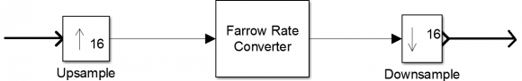
Thanks for the advice on upsampling to reduce complexity. I've read about it in Fred Harriss's book. When I saw my in-bound noise is high, I decided to do the same. Currently, I upsample by a factor of 16, resample by first order Farrow, and then downsample by 16, just to avoide nonlinear phase property of higher order Farrow filters.
I don't have a definite answer for other detailed questions about how PPS is sampled,etc. We thought these will be decided later.
Your proposed solution of the NCO is really nice and comprehensive. It is the dream comes true if I can handle it. Would you please provide a bit more information, or point me to some references (papers, books, etc) on NCO?
Kind regards,
Morteza
Hello Morteza,
Unfortunately I don't have any specific references for the NCO specifically other than general references on PLLs. It's not hard once you see it. I'll post a Simulink example using a fixed NCO.
So the signal is limited to 4.5 kHz and Fs = 13 kHz. That's more than Fs/4 so upsampling is the way to go. You haven't said what you sink sample rate needs to be. It matter for the NCO and PLL design. Also, is the sink domain synchronous with the PPS signal? It can just be an enabled domain. If that PPS has a good fast rising edge you might consider using as a clock input. It can clock a T flip-flop. That square wave can then be the phase reference for the PLL.
As far as higher order Farrow filters, they have *less* phase distortion with increasing complexity, not the other way around. Since you are upsampling by 16 then Fs = 208 kHz and the signal down around Fs/64. I think I would use a quadratic rather than 1st order.
Cheers,
Mark Napier
Dear Mark,
Thanks for the quick reply.
Sorry, that I missed mentioning my output sampling rate. It can be anything between 10240.256 kHz up to 18000 kHz (0.256Hz resolution). It is continuously changing almost every second.
PPS comes from the GPS receiver, so I believe it would be quite accurate and stable with sharp edges.
My current plan is depicted in Figure below. Upsample X16, Farrow filter, and then downsample by a factor of 16. Of course, both upsample and downsample filters will be implemented in the polyphase form to reduce the computational cost.
I've read some papers and patents on NCOs. But I cannot figure it out how do you mean I should use it to readjust the Farrow filter. Would you please post a diagram here to clarify the solution. Alternatively, I can be reached via email:
morteza.shahpari@ieee.org
Thanks a lot for your attention.
Kind regards,
Morteza
Hello Morteza,
I'll post an example. Today is really busy but I'll try get to it.
A Farrow filter needs a term called "mu" which has a value of [0,1), that means from "0" to just 1 LSB from "1". It is the interpolation distance (fraction) in-between the 1st sample to the 2nd assuming that you are just doing linear interpolation between two samples. More generally it is distance in-between the sampling interval.
So the NCO is set to some nominal frequency. The NCO is represented by an unsigned value also on [0,1). Every time the NCO rolls over pull a sample from the Farrow filter. Take the upper N bits of the NCO, however many bits you are using for "mu", and that is the fractional delay for the filter.
In principle the Farrow filter certainly can be used to decimate. With the stated output range I think the way to do it is upsample by 16, use the variable interpolator to go down by ~2 and finally decimate by 8.
So the output rate is from 10.2 kHz up to 18 kHz? Does this vary quickly? Hate to state the obvious but with PPS you only get an update once a second. Also the PLL will have a settling time proportional to the noise bandwidth. How closely does it have to track? This sounds tricky.
What is pulling the output samples? Is it at all synchronous with the PPS? If not then there are two problems. One is to produce retimed samples in the output domain. The other, if I understood, is to produce one sample that is exactly timed with the PPS signal. That sounds like a separate filter.
Cheers,
Mark Napier
sorry to say but I am lost... is this task about clock crossing or is it about resampling input to different rate or just synchronizer.
if it is clock crossing then you can use fifo and it is all done.
input writes to fifo and output is read back by some unknown clock?
if it is resampler then you need to create or drop samples plus fractional delay. your input sample rate is defined but your output rate is not defined apart from saying that one sample at output should coincide with pps. If so it is not a resampler in my view but something else which I can call synchronizer.
Thus you have three possibilities to define the requirement. I think it is unfair to jump to any solution for an unknown requirement.
I agree with you.


