


Matlab-implementation of dynamic range compressor
hey guys,
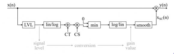
I am trying to implement a dynamic range compressor in Matlab according to the following block diagram:
The problem is, I don't understand the block diagram.
However, I have a vague understanding of compression: Whenever the amplitude of my audio-signal exceeds a threshold, the output gets reduced by a factor CR (compression ratio).
Also: The LVL-block should correspond to a peek-detector, which is basically a first-order IIR-filter and may be implemented as:
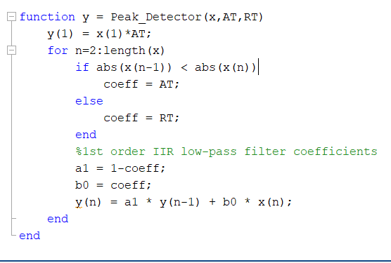
The smooth-block can be implemented the same way, with the only difference being the condition of the if-statement, which gets changed to: abs(x(n)) < abs(y(n-1))
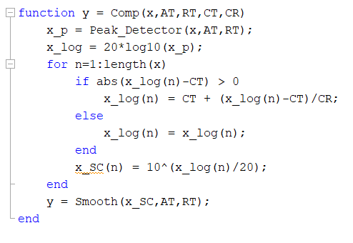
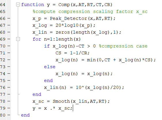
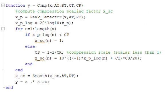
And based on these assumptions, here is my try to implement the compressor:
Unfortunately, this doesn't work. And I can't figure out why, for the hell of it.
If anyone could help, that'd be great!

I'm just going to look at the diagram and describing everything - some obvious, some maybe not...
The mapping between input level and output level is being done in the logarithmic domain, so...
1) The level of the incoming signal is estimated with LVL
2) A conversion is made from linear to log
3) The signal is offset by some compressor threshold (CT)
4) The signal is scaled by some compressor scale (CS)
5) The lower bound of 0dB is forced
6) The compressor scaling factor it mapped back to the linear domain
7) It is put through some smoothing filter to minimize discontinuities in the output due to rapid changes in the scale factor
8) The incoming signal is scaled by the compressor gain
I'm not advocating this diagram. Just describing it.
The possibly confusing part is that the compressor is linear in the log domain. CT and CS are the equation of your line. Gy=CS*Gx+CT. ...with Gy and Gx in dB.
The part in the middle could have been managed in the linear domain. It also could have been processed with a function or lookup table that provided more unique/customized processing. As such, the diagram is not as general as it could have been.
__________________________
Edited to add...
In looking at your code, I suggest that you reconsider two lines:
1) if abs(x_log(n)-CT) >0
The absolute value is never less than 0, so you are forcing your compression case which is:
2) x_log(n) = CT + (x_log(n)-CT)/CR
For that line, please remember that you are in the log domain. This line implements linear processing of the logarithmic representation of the signal.
If you look at the block diagram above, they are performing the actual scaling in the linear domain. Only the calculation of the scaling factor is in the logarithmic domain. That differs from your approach.
thank you so much for your help!
Let me try and get this right, though:
1) is forcing the compression case, you are absolutely right about that, and I have corrected it to:
if x_log(n)-CT > 0
This should give the compression case. And now you are saying that compression should be performed in linear domain. This is what I don't understand. In the block diagram, after the LVL, we are switching to logarithmic scale. And then we add CT and multiply by CS. So maybe my equation is wrong and should be correcte to
x_log(n) = CT + x_log(n)*CS
with CS = 1 - 1/CR
This, however, is still performed in logarithmic scale (decibels). So, sorry to say I still don't quite understand what you are trying to tell me here.
And I have still troubles understanding what the min-Block is about. You have written that this part forces a lower bound of 0dB. I figured it might tell me to take the minimum of my scaled signal and 0dB, i.e. to basically only consider positive dB-values. This doesn't make any sense to me, however.
For the second line of code that I called out, I was trying to make a two distinct points. I'll state them again - both differently and in swapped order - in the hopes that it might be more clear.
The people who drew the diagram have the signal modification entirely in the linear realm. Y=Xc*X - where y is the output, x is the input, and Xc is their compression coefficient. At no time is X converted to its logarithmic representation for the purposes of signal processing.
The lower branch of the diagram - that calculates the compression coefficient - bounces in and out of the logarithmic domain. Is that good? Well... it is good in the sense that they can do crazy stuff and - after lowpass filtering the output of their map - it won't damage the input too much. Stated more technically, their compression artifacts are desensitized to their manner of compression calculation.
You did not implement in that way. You are bringing your input into the logarithmic domain and trying to scale within. That means that any craziness that is a component of your compression algorithm is going to have an immediate, profound, and nonlinear impact on your output signal.
The other point that I tried to make is that you are scaling your signal linearly when your signal and scaling factor are both in dB. That doesn't work. Multiplication in the linear domain is addition in the logarithmic domain.
y=K*x -> y(dB)=K(dB)+x(dB)
You have converted your input to a logarithmic representation. You have generated a compression coefficient that also is logarithmic. I don't know what multiplying them gets you in a practical sense, but I can safely assume that it's not what you want!
...and even after that I do not see a proper conversion back to the linear domain. fred mentioned this. I'd tell you to fix it but I don't think that you should be generating the output from a converted form of the input in the first place.
My recommendations:
1) Read fred's paper
2) Recast your m-file to calculate the compression scaling coefficient completely separate from the input/output stream (i.e., leave the signal in its linear form.)
3) Strip out attack and release for now. Just make it an instantaneous compressor. You can sort out the transitions after it is behaving.
4) First, test your code with pure tones of various fixed magnitudes.
5) Then, test your code with a tone that is modulated by a ramp (gradually linearly increasing magnitude). Watch the threshold behavior.
6) Add back in attack and release.
_____________
Last comment... you asked about the 0dB limit and the use of division rather than multiplication in the scaling. This pic might make it more clear:
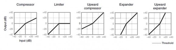
You/they are implementing a compressor. As such, the point of 0dB should be clear. Everything hinges on 0dB.
For your strict compressor, the slope is less than one for the upper right quadrant. If you were implementing an upward expander, you would have a slope greater than one for the upper right quadrant. The same code should do either.
So... your conclusion that it is all the same is correct. One person's "2" is another person's "1/0.5".
Hope this helps.
I will have to think about this for a lil while longer.
still: Can I compute the scaling factor just according to the block diagram, as I did in line 72 ?
Because if this correct now, I know I must have another error in either the Peak_Detector or the Smooth function.
Your question is: Can I compute the scaling factor just according to the block diagram, as I did in line 72 ?
The answer is yes to line 72. ...but your naming convention isn't helping. ...and what's around it still doesn't look right to me.
At the core of your compressor - and the block diagram - is the idea that:
X_sc(dB)=CS*Xlvl(dB)+CT(dB)
It is saying that the scaling function is a linear map of input level to output level. That is what we see in the leftmost figure of the image that I posted. That is correct.
Your line 72 is that same equation plus the min function - that isn't really doing anything for you since your if(l_log...) already established that the instantaneous output of your peak detector is > 0dB.
First: naming conventions...
x_log isn't the log of x. It is the log of your peak detector output. Similarly, x_lin isn't related directly to x but to x_p - the output of your peak detector. You may want to go with:
x_log -> x_p_log and x_lin -> x_p_lin.
...or something like that.
Second: the algorithm
I think that the block diagram is doing a disservice to you because it more describes the spirit of what they are doing rather than actual operations.
So... let's implement a compressor that has a 0dB break point and a compression scaler/slope of 1/3. It will accept a block and scale that whole block by one compression scaler as determined by the peak magnitude of that block.
I am ignoring the compression threshold because we have already decided that it is 0dB. I am also ignoring attack and release time because they will only confuse things.
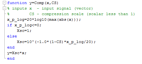
My core equation differs from yours. I have a -1.0 multiplier because I want to attenuate and we're in the logarithmic domain. ...and that's how it's done. (1-CS) is my desired attenuation magnitude (e.g., if I want my signal to be 25% of the input level, I need to attenuate by 75%. This could be recast in other ways, of course.
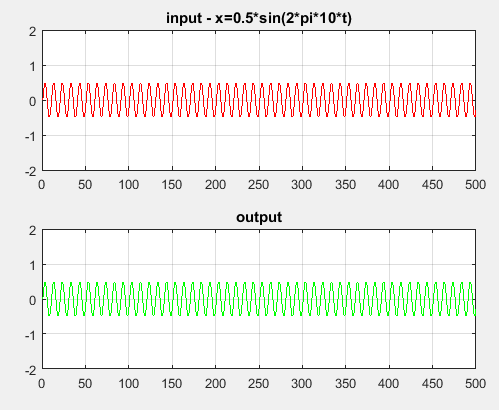
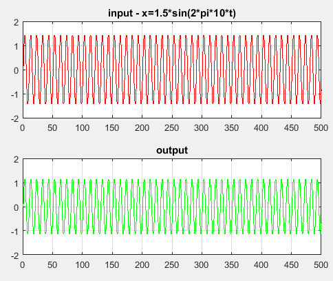
If I put in a 10Hz sine wave (x) with a peak value of 0.5 (roughly -6dB), it passes unscathed. If I put in a 10Hz sine wave (xx) with a peak value of 1.5 (roughly +3dB) it is scaled to 1.125 (roughly +1dB or 1/3 of the excess gain above 0dB).
Here are my two calls:
y=Comp(x,0.333)
yy=Comp(xx,0.333)
...and here are my two I/O plots:
I am sure that you will get yours working. First, get your code to map simple cases such as what I showed. Then, put everything else around it.
cool, thank you so much, you saved my life!
I have got it to work. Here is the Comp-function again, just in case you are interested (but I just did what you suggested anyways):

Where did you find the block-diagram?

This idea, as a general concept, is the essence of mu-law or a-law coding.
The second log/ln block is the inverse log... you have to undo the input log...
you have a feed forward system... might want to consider a feedback option.
look at the block diagram in the attached pdf and see agc paper...
by the way, if signal is real, might want to use Hilbeert transform to get complex envelope and use Mag of envelope to operate gain control.
fred harris


