


and coeffs:
den = [-2.86512631333559 1.915296632059649 4.86512631333559]
num = [-14.38734500433902 1.915296632059649 16.38734500433902]
Phase response is wrong so, to turn the phase I did change the sign of the variable Q and got the right responses:
den = [4.86512631333559 1.915296632059649 -2.86512631333559]
num = [16.38734500433902 1.915296632059649 -14.38734500433902]
Is this correct way to turn the phase response?
I noticed the 'mirrored' coefficients but not sure what it means. Is the Octave showing correct magnitude plot for both filters?
I'm using this Octave script:
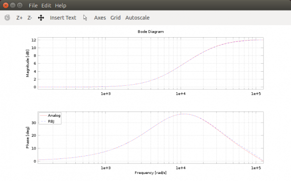
% Octave packages -------------------------------
pkg load signal

% filter parameters -----------------------------
fs = 44100;
fc = 20000;
Q  = 0.089084;
db = 12.0;

%% Analog prototype (RBJ EQ Cookbook formulas) --
K  = 10^(db/40);
QA = K*Q;
wA0 = 2*pi*fc;
BA = [1 K^2*wA0/QA wA0^2];
AA = [1 wA0/QA wA0^2];

A = tf(BA,AA);

%% Q inversion ----------------------------------
%Q=Q*-1.0;

% Q pre-warping ---------------------------------
% use the one from https://www.google.fi/?gws_rd=ssl#q=RobClarkPhD.pd...

%% Digital filter (RBJ EQ Cookbook formulas) ----
w0 = 2*pi*fc/fs;
cw0 = cos(w0);
sw0 = sin(w0);
alpha = sw0/(2*Q);

b0 = 1+alpha*K;
b1 = -2*cw0;
b2 = 1-alpha*K;
a0 = 1+alpha/K;
a1 = -2*cw0;
a2 = 1-alpha/K;

BD = [b2 b1 b0];
AD = [a2 a1 a0];

RBJQ = tf(BD,AD,1/fs);

% bode plot -------------------------------------
wmin = 2 * pi * 20; % 20Hz
wmax = 2 * pi * ((fs/2.0) - (fs/2 - 20000)); % 20kHz

bode(A,'r', RBJQ, '--',{wmin, wmax});
legend('Analog','RBJ case Q w/ Q pre-warping','location', 'northwest');

Hi jtp_1960,
In my MATLAB modeling of your *first* set of feedforward and feedback coefficients, I obtained the same magnitude and phase plots as you provided in your question. (I'm not familiar with "RBJ's cookbook", so there's no way for me to detect any possible errors in your OCTAVE code.)
jtp_1960, you didn't tell us, ...do you consider the phase plot you provided in your question to be "correct" or "incorrect"? Also, I've never read the phrase "turn the phase response" before. What does that mysterious word "turn" mean?
Hi, and thanks for the reply.
RBJ's EQ Cookbook paper - http://www.musicdsp.org/files/Audio-EQ-Cookbook.tx...
With "turn" I mean "invert" (turn 180 degrees if one can say it this way).
My guess is that the phase shown in first plot is incorrect because of when I plot the responses of same filter build using other methods (orfandis, original RBJ case Q and case BW, etc.) these all have phase response at positive side of axis (as like the analog prototype does). If the phase response for my analog prototype is wrong then my guess is incorrect as are those other filters as well. (I have to mention that I'm at beginner stage with DSP and Matlab/Octave).
Anyway, as seen in plot, changing sign of the Q inverts the phase response. Is it correct method to do it this way or is there something more done in background one can't see in plot (if those two sets of coefficients are summed and then divided by two the resulting coefficients give flat response for both magnitude and phase).
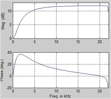
Please forgive me. I made a mistake in my first Reply. When coefficients:
den = [4.86512631333559, 1.915296632059649, -2.86512631333559]
num = [16.38734500433902, 1.915296632059649, -14.38734500433902]
are used in a digital IIR filter, the freq magnitude and phase responses are as follows:
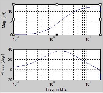
If you prefer the freq axis to be logarithmic, then the above digital filter curves look like the following:
Warning: When used in a digital IIR filter, the first set of coefficients in your original post produce a pole outside the unit circle on the z-plane. So those coefficients yield an unstable digital filter, and must therefore be incorrect.
As for the phrases "turn the phase" and "invert the phase", I suggest you not use them. The phrase "negate the phase" is more correct.
Now to the interesting part of your post. Reversing numerator coefficients and reversing denominator coefficients does appear to yield a conjugated frequency response (a frequency response with unchanged magnitude but negated phase). I don't think I've encountered this idea before, and off the top of my head I can't explain why that happens. I'll have to think more about this 'reversal of coefficients' operation.jtp-1960, you do not design a digital filter (i.e., compute its feedforward & feedback coefficients) and then reverse those coefficients to obtain your desired filter. You need to figure out how to obtain the correct coefficients in the firsts place. Your job is to double check the "cookbook" equations and double check you software code to see why negating that 'Q' value gives you correct coefficients.
Thanks!
Yes, I'll have to double check if the adopted RBJ's cookbook design is correctly implemented in my script.
Script I'm using for plots is originally done for Matlab (I took only those parts needed in this case) and also did found out that it is possible Octave plots the analog prototype differently from what Matlab would do (shouldn't the phase-shift be negative?). So, partly this case may relate to differences between those two software packages. I need to dig this more.

I don't see dc gain normalised. Moreover we need to add 1 to first den(once normalised)
Kaz
Hello Kaz,
Will you give us more details on what you have in mind? Thanks.
apologies, the terms are indeed normalised for dc gain since sum(num)/sum(den) = 1.
However matlab convention is that the first recursion term is set to unity. this avoids confusion of the signage especially so at implementation. The first recursion term then is a direct wiring of feedback without a multiplier.
I normalised the posted coeffs in that conventional way and ended up with same response.
Kaz
For FIR filter with coefs C1 = = [b0, b1, b2] and Z-transform H1(z) = b0 + b1 z^-1 + b2 z^-2, reversing coefs gives filter C2 = [b2, b1, b0] with H2(z) = b2 + b1 z^-1 + b0 z^-2 = H1(1/z) * z^-2.
w = digital-freq, j^2 = -1.
So angle{H1(z)} = angle{H1(e^(jw))} and angle{H2(z)} = angle{H2(e^(jw)) e^(-j2w)} which may be the cause for "negated phase response".


