


ADC and Complex Mixer Nyquist question
Hello,
So I am struggling with a fundamental Nyquist bandwidth question. My SOC consists of a high-speed ADC followed by a complex mixer (with optional decimation).
Say my Sampling Rate of the ADC is 1GHz, I know my first Nyquist zone is 0 to 500MHz, or that my effective bandwidth is 500Mhz, and everything above that will fold into the first Nyquist zone. Now when when that ADC output hits the complex mixer, I get I/Q samples at 1Ghz. I am used to thinking of Nyquist bandwidth of a complex signal = Fs (1 GHz in this case). I know typically after the complex mixer (tune), there are decimate and filter stages, and so let's say I decimate by 8, the effective bandwidth is 125MHz (1G/8) - the 125MHz bandwidth after decimate-by-8 makes sense. But what's the best way to reconcile the 500Mhz BW of ADC sampled signal with the 1GHz BW after the complex mixer? Is it just that the theoretically I can represent 1GHz after adding the quadrature component (canceling negative frequencies et. al), but realistically feeding a 600MHz signal into the ADC will fold it to 400MHz, so the theoretical doubling of capacity due the complex mixer is not used until further decimation?

Here's how I'd approach this: Assuming that your ADC is sampling just a real signal, the complete spectrum of this can be viewed as 0-500MHz of the real signal, plus 0 to -500MHz of the inverted spectral image of the real signal.
Once you pass this through a complex mixer, all you're doing is sliding that spectrum+image around by the frequency of the local oscillator. Any filtering and decimation you do after that is just selecting the two-sided bandwidth of the filter centered around DC, and DC is really centered on the local oscillator frequency of the input signal. So if you tune positive, you'll recover signals in the 0-500 range. If you tune negative you'll still recover the same signals, but they'll be spectrally inverted. There is no theoretical doubling of frequency - it's the same signal, just inverted.
As you noted, when you feed a 600MHz signal into your 1GHz ADC, the portion beyond Nyquist in the 500-600MHz range will fold down over the portion from 400-600, making that region ambiguous and likely useless. You can still recover usable signal from the 0-400MHz region however.

Another approach: imagine a complex signal, having two components, if we look at it in Cartesian representation: (real,imag)
Now you feed your system (through ADC) with a signal you could represent as (adc,0) meaning that your ADC provides a signal which you say is the real part of the signal, while you implicitely declare the imag part to be 0 (always).
The more general case might have another signal as imag part, giving (adc1,adc2) as a complex signal. Quite obviously you have 2xBW(adc) here.
Mathematically both signals are independent (orthogonal), so you have 2xBW(adc).
Rotating this signal in the complex plane leads to the view of "emeb".
I/Q representation is basically nothing else as the Cartesian view.
It has nothing to do with gaining Bandwidth or additional frequency content.
Your mixer, however, will change something with the frequency content.
But this is again, pure trigonometry, not any real "gain".

Hi sachinwannabe.
Let's say the output of your ADC (Fs sampling rate of one GHz) is a real-valued x(n) sequence whose |X(m)| FFT spectral magnitude is shown below in Fig. 1(a). Because x(n) is real-valued we see the spectral mirror-image symmetry centered at zero Hz. The total freq range of |X(m)| is -0.5 Ghz -to- +0.5 Ghz, but because of that mandatory symmetry our usable freq range is only 0.5 GHz. That is, x(n) can only have independent spectral components in the range of 0 -to- +0.5 GHz.

Fig. 1
Because of the periodic nature of the FFT, I sometimes find it convenient to redraw |X(m)| around a circular frequency axis as given in Fig. 1(b). Now if you wanted to isolate (for possible follow-on processing) the spectral energy centered at fc Hz you would apply your x(n) sequence to the complex mixer shown below in Fig. 2(a). Now you've produced a complex-valued xc(n) sequence whose |Xc(m)| FFT spectral magnitude is shown below in Fig. 2(b).
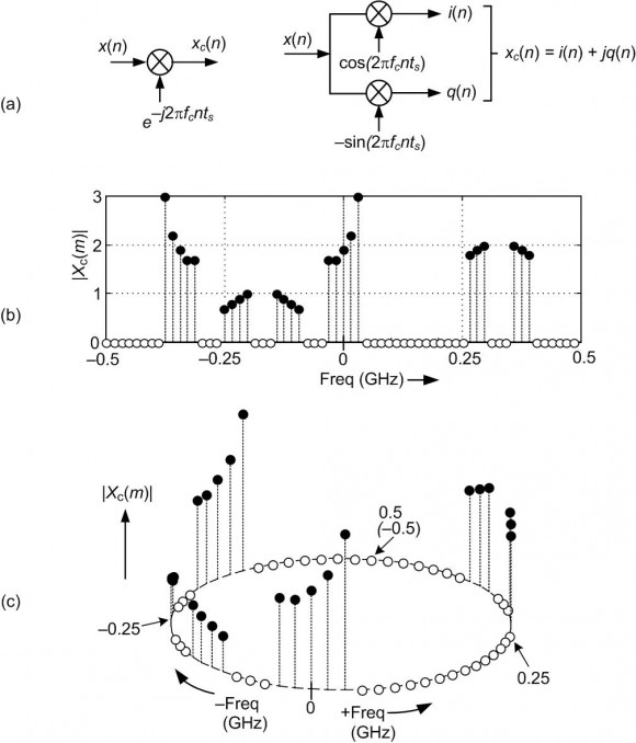
Fig. 2
Because xc(n) is complex-valued its |Xc(m)| spectrum need NOT be symmetrical centered at zero Hz. Sequence xc(n) can have independent spectral components anywhere in the one GHz range of -0.5 Ghz -to- +0.5 Ghz.
Given that you now have the complex-valued xc(n) sequence, you can apply its i(n) part and its q(n) part to two separate lowpass filters in anticipation of decimation.

Hi Rick,
You say "Sequence xc(n) can have independent spectral components anywhere in the one GHz range of -0.5 Ghz -to- +0.5 Ghz.". Since we shift the spectrum to the fc and -fc by multiplication of sinusoids (multiplied by different constants for cos and sin of course), is it appropriate to say independent components here?
Also, unrelated question but what program did you use for plotting figure 1-b and figure 2-c ? They are very nice.
Hi omersayli.
First, we don't "shift the spectrum to the fc and -fc". We shift X(m)'s spectrum in the negative-frequency direction by fc Hz. What I hoped to convey with my "independent spectral components" phrase is: The positive-frequency and negative-frequency spectral components in X(m) are not independent of each other. They are complex conjugates of each other. On the other hand, the positive-frequency and negative-frequency spectral components in Xc(m) are independent of each other.
My Figure 1(b) and Figure 2(c) were plotted using some clumsy MATLAB code threw together while writing my "Understanding DSP" book. I can send that code to you if you wish.
Hi Rick,
Sorry, of course your Xc(m) is negative shift by fc (I stated sinosoids but missed total signal xc(t)-Xc(m))
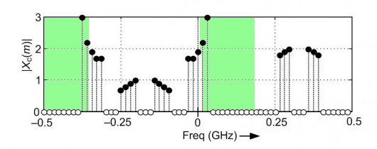
My point was that as you have stated X(m) have even magnitude and odd phase symmetry about the 0 Hz. But even after you shift this spectrum to the negative frequency direction by fc, you would have "dependent" frequency components between -0.5- 0 Ghz region and 0-0.5 Ghz region,, because of circular shifting of course. But the "correlated"( better word?) frequencies would not be plus/minus of same value of frequencies. I hope the below coloring on your figure helps to clarify my point.
The following is the spectrum of the real-valued x(n) sequence.
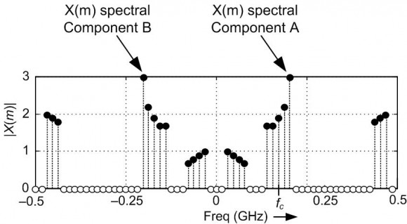
If I performed passband filtering of the x(n) sequence to attenuate the X(m) spectral component A, then the X(m) spectral component B would also be attenuated. X(m) spectral components A and B are NOT independent of each other.
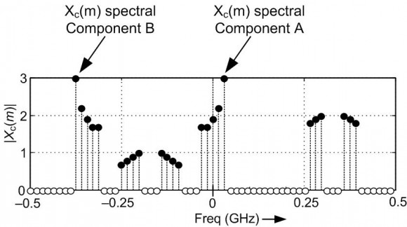
The following is the spectrum of the complex-valued xc(n) sequence.

Rick-
That is an exceptionally intuitive explanation. Mixing is rotating after an FFT, I did not think of it that way before. Thanks.
-Jeff
Hi ,
Assuming communications signal (?), I want to remind , a baseband signal of interest with a much low frequency content (Bandwidth) -compared to carrier frequency- is to be shifted to a much higher frequency for transmission. Now the 0 hz would correspond to carrier frequency in the modulated signal (of course, speaking very very generally)
The purpose is by ADC and decimation is for getting back this baseband signal with much lower bandwidth compared to carrier frequency. After low pass filtering, decimation is used since recovered baseband signal has much lower bandwidth.
In short, mixer is there for baseband signal recovery (centered around carrier frequency - speaking simplified), not for Fs/2 bandwidth signal actually.
These links could help
http://www.vppsim.com/BasicCommLectures/lec4.pdf
https://dspillustrations.com/pages/posts/misc/baseband-up-and-downconversion-and-iq-modulation.html

With full respect to all useful replies I will answer with an analogy:
The main entrance door(real ADC) allows one slim man to get through but the inner door(complex mixer) allows double size man.
Kaz
Everyone,
Thanks for your replies.
My fundamental confusion was how to reconcile with the "additional" bandwidth that comes the I/Q conversion - the mixer is bit of a distraction. So if I was using a Hilbert transform at the output of the ADC, with no frequency translation - the A/D running at 1G Nyquist first zone would be 500MHz, but after the I/Q conversion @ 1Gsps 1Ghs "could" be represented - just that the 500M to 1GHz zone would have no energy.
Every thing else about mixers, decimation, tuning folks have cared to explain I am with you.


