


Controlling a DSP Network's Gain: A Note For DSP Beginners
This blog briefly discusses a topic well-known to experienced DSP practitioners but may not be so well-known to DSP beginners. The topic is the proper way to control a digital network's gain.
Digital Network Gain Control
Figure 1 shows a collection of networks I've seen, in the literature of DSP, where strict gain control is implemented.
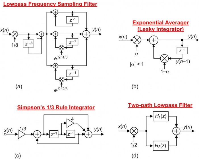
FIGURE 1. Examples of digital networks whose initial operations are input signal attenuation.
Focusing on the network in Figure 1(a), I encountered that lowpass filter block diagram while studying the subject of frequency sampling filters described in a popular college DSP textbook. Such a filter would normally have a passband gain of 8, and in order to force the filter's passband gain to be equal to one the authors included the 1/8 multiplication operation at the input of the filter.
To be clear at this point, that 1/8 multiplication in Figure 1(a) is NOT some type of "filter scaling" meant to avoid arithmetic data overflow. The 1/8 multiplication merely ensures unity-gain in the filter's passband.
Assuming Figure 1(a)'s x(n) input was generated by an A/D converter and we're using fixed-point arithmetic, such a gain control method would discard the three least significant bits of the x(n) input sequence. Such a gain control method decreases the resulting input's signal-to-quantization-noise ratio (SQNR) by an unacceptable 18 dB.
Input signal bits are valuable. Don't throw them away! For proper implementation, the preferred gain control method for Figure 1(a)'s filter is to place the 1/8 multiplication at the output as shown in Figure 2(a). And that guidance is main point of this blog; attenuate a network's output sequence, not its input sequence. The other networks in Figure 2 illustrate properly implemented gain control.
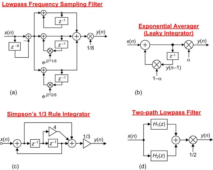
FIGURE 2. Digital networks where the gain is adjusted by a final multiplication stage.
A Warning
It was some days ago when I encountered the Figure 1(c) Simpson's 1/3 Rule digital integrator (repeated here as Figure 3,) in a book discussing biomedical signal processing. It was this network that prompted me to write this blog.
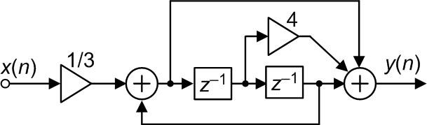
FIGURE 3. Incorrect implementation of a Simpson's 1/3 Rule integrator.
Figure 3 is an attempt to implement a Simpson's 1/3 Rule integrator transfer function defined by the following:
$$y(n) = \frac{[x(n)+4x(n-1)+x(n-2)]}{3}+y(n-2)$$
My warning is: the Figure 3 network does not compute correct Simpson's 1/3 Rule integration results. I haven't yet created a correct block diagram for a Simpson's 1/3 Rule integrator but if I do it will not have a 1/3 multiplier at its input.

- Comments
- Write a Comment Select to add a comment

Hi Rick,
I am unable to understand what the problem is in the first place.
The fraction of alpha and (1-alpha) are written on diagrams to describe the system. In reality the implementation depends on platform. For fixed point(ASIC/FPGA) if alpha = 0.013 as example then we scale it say to 0.013 *2^15 and same for (1-alpha). and finally we scale down the result by 2^15 (discard 15 lsbs).
For floating point there is no worry of losing bits.

Hi Kaz.
The problem is the degradation suffered by an input signal's 'Signal to Quantization Noise Ratio' when the very first operation of a digital system is attenuation.
Kaz, please forgive me. I'm not familiar with the peculiarities of ASIC/FPGA implementations. I don't understand what you meant when you wrote, "For fixed point(ASIC/FPGA) if alpha = 0.013 as example then we scale it say to 0.013 *2^15 and same for (1-alpha)." Are you saying: In FPGAs, if we want to multiple a discrete sample by decimal 0.013 then we would actually multiply that sample by decimal 0.013*2^15 = 425.984?
Hi Rick,
Yes we convert the fraction of 0.013 to 426 (rounded) using scale factor of 2^15. This scale factor is up to designer. If you want mathematical unity then you divide back by 2^15 at some final output allowing full bit growth inside a given module. This also applies to any multiplication including products of filters as each coeff is scaled internally, multiplied, summed given full bit growth, finally truncated by discarding lsbs plus any rounding.
This power of 2 approach avoids using dividers which are slow and resource demanding. However I have seen many beginners learn the wrong way and use dividers.
In all cases we scale fractions to integers though some tools prefer to use fractional notation as if software, yet internally it is just a data bus with imagined decimal point(in above case the decimal point could be at bit 15.
In the same way we can divide by a constant by converting the operation to pre-scale then multiply then divide in hardware through truncation
I am curious why you focussed (rightly) on scaling of input with alpha but not y with (1-alpha) which is also fraction.
Hi kaz.
You wrote, "I am curious why you focussed (rightly) on scaling of input with alpha but not y with (1-alpha) which is also fraction." The point of my blog is nothing more than the following: Scaling a DSP system's gain by attenuating the system's input signal, prior to performing any follow-on computations, should be avoided if possible.
Hi Rick,
The principle itself is sound advice. But the example given is open to different views.
My view is that I will keep integrator feedback gain under control by applying traditional alpha and 1-alpha inside feedback loop then scale down the output outside loop. Otherwise it could shoot up at very low values of alpha.

Hi Rick,
I think your post demonstrates very neatly how two seemingly equivalent theoretical designs could give rise to vastly different performance in the implementation.
As you note, this kind of consideration is very well known and any implementation engineer worth their salt would weigh up the trade-offs. The reason I say it's a trade-off is that - for the cost of the 18dB degradation you mention - you have bought cheaper adders, multipliers and delay elements through the rest of the network. (It's always cheaper to add, multiply and delay narrower bit-widths in ASICs, and often in FPGAs too, with some caveats).
As you say, 18dB may be an unacceptable degradation in performance. But if you are also constrained by area and/or power requirements, then you may have to do some scaling at the start, some in the middle and some at the end.
But as an introductory article, I think your blog highlighted the key idea very concisely and was a joy to read.
Harry
Hi weetabixharry. Thanks for the compliment, but I must confess. The Exponential Averager in my Figure 1(b) comes straight out of my DSP book's Chapter 11. Years ago when I first studied exponential averagers I naively repeated the literature's typical block diagram as the averager's block diagram for my book. At that time I was thinking analytically rather than practically.
Hi Rick, I believe that in many fixed-point systems the input gain does not throw away bits in the way you describe because the signal path is running with more fractional bits that what is coming from the ADC. Or if this is not the case then an input gain may be required to avoid wrap-around.
Hi niarn.
Is there a web page were I can see an example of what you call "running with more fractional bits that what is coming from the ADC"? I'm not sure what your word "running" means.
Any division by $2^n$ can be considered implicit in a fixed point system. In other words, you do nothing but just remember that the meaning of the number has changed (i.e. has more fractional bits).
For example, let's say the input is 100.75, represented as a 16-bit two's compliment signed number with 4 fractional bits:
0000011001001100 (64 + 32 + 4 + 0.5 + 0.25)
We could even insert a binary point if we want:
000001100100.1100
Then if we divide this number by 8, we get:
0000011001001100
or with the binary point:
000001100.1001100
The bits are exactly the same, but now the meaning is 8+4+0.5+1/16+1/32 = 12.59375.
If we divide by something other than $2^n$, we can still increase or decrease the number of overall bits after the division. For example, if we divide 100.75 by 3 instead of 8, then we will get:
000000100001.10010101010101010101010101010... = 32+1+1/2+1/16+1/64+...
It's up to us how many repetitions of "10" we want to keep at the end.
Hi Rick,
In my experience, this concept is extremely widely used in FPGAs and ASICs. For a fixed (i.e. fixed at compile time) multiplication or division by $2^n$, the cost in terms of hardware resources (and power consumption) is exactly zero because the position of the binary point is not represented in any way in hardware. It’s something the designer has to keep track of and manage appropriately. This can become surprisingly difficult after even just a few stages of processing (where each stage may change both the physical bit-width and the conceptual position of the binary point).
If your $2^n$ is not fixed at compile time, then the cost could still be very small, but not zero. For example, if you’re not sure if you will need to divide by 8 or 16, then – abstractly speaking - you need some way of representing in the hardware which route was taken. The naïve way would be to literally “compute” two separate right-shifts: one right-shift by 3 bits (cost = zero), one right-shift by 4 bits (cost = zero), and then select the one you want using a multiplexer (cost > zero).
That approach is naïve because it blindly assumes that you want your physical bit-width to stay the same and that you want the conceptual binary point to remain in the same place. In some cases, that might be the best design choice, but not in general.
In some cases, it might be better to do no explicit shifting and instead just keep record (in hardware, alongside your original number) of all the implicit left and right shifts that accumulate over time. This is essentially what floating point representation is for (the mantissa records the number and the exponent records the bit-shift). Unfortunately, arbitrary floating-point arithmetic is significantly more expensive than fixed point (addition, for example, costs vastly more). So, again, it’s up to the designer to use it in the right places.
Hi Rick,
As words of "comfort" from a semi-retiree to a retiree, though I haven't done micro-controllers or soft dsp but I expect no difference between FPGA and software when it comes to fixed point computations...except for terminology.
Software tends to describe fractions "as is" or in Q format. fpga/Asic uses that or integer interpretation. software uses the term "shift" for multiply or divide by 2 but fpga/Asic do/may not as they don't have to shift but rather insert a zero or chop off a bit, unless they want to if data width is meant to stay.
I believe both are valid but here is an example when software terminology does better job. I want a mixer so I generate frequencies from an NCO. The dynamic range is +/-1 but fpga had to pre-scale that to 2^n then divide result of hard mixing by 2^n...Now I want another NCO to generate frequency of Fs/4 only, in the range +/-1 (1,0,-1,0...etc), this tells me don't pre-scale it but just pass sample1,set sample2 to 0, invert sample3 ...if I scale it I am wasting my time and resource.
So in short any fraction given for a design translates up by pre-scaling on FPGAs but any complete integer stays. For a fraction whether we name it as Q format or integer is a matter of taste but eventually that pre-scaled integer must be hardware scaled down to give the fractional weight at result.

Hi Kaz,
I agree that the "Q" terminology is common and useful. I choose to use the terminology A(a,b) (for signed) and U(a,b) (for unsigned), where "b" is essentially Q for my work because it carries a bit more information (pun?), namely, the total word width can be determined by a and b; not so with Q.
However, I admit that I've never seen it used outside of my own work other than some specifications I worked with from Lincoln Labs back in the 90s.
--Randy
I disagree that it is so widely used, unless the fixed-point implementation is computer generated (can be done with a floating-point model and a lot of unit-tests).
In 'hand-made' systems, this kind of dynamic decimal point shifting gets out of hand very fast - it becomes a risk to your mental health! You have to protect against overflow and loss of precision.
Better way is to use constant decimal point. Commonly used FPGA format has 18 bits - 1 for sign and rest for fraction (represents numbers in -1 .. 1 range). So if my ADC has 12 bits, i already have 6 bits of `computational headroom`.
Now, about the original post - system has a gain, thus the input must be compensated or we risk overflow (don't do this).
There are three ways to solve the problem:
1. Truncate excess input bits - bad, results in negative bias - but free.
2. Round excess input bits - usually good enough - but expensive.
3. Add guard bits to protect against overflow - this allows you to scale at output - but you still have to round when you are throwing away the guard bits.
I prefer the 2. method but the 3. method is more accurate and may be necessary if you need to demonstrate `equality` against the floating-point model.
Thanks for your April 25th "Comment". You've made me finally realize why some of the Comments to my blog puzzled me so much. I see my mistake.
In the original version of my blog I used the words "scale" and "scaling" improperly. My use of those words may have caused the some readers here to unconsciously assume my blog topic was "filter scaling to avoid arithmetic data overflow." And that was NOT the topic of my blog. (I've reworded my blog to eliminate the words "scale" and "scaling.")
The point of my blog was: To control a digital network's gain, don't attenuate the network's input signal. Attenuate the network's output signal.
Hi Rick,
I know this technique of "reinterpretation" for implementing power-of-two multiplications and divisions, i.e., shifting, in fixed-point arithmetic is common and powerful, precisely for the reasons that a) it consumes zero computational resources and b) it perfectly maintains the input signal resolution. I describe it in section 5.12.2, "Virtual Shift" in my paper.
I don't think you can separate fixed-point techniques into FPGA and other (e.g., software/firmware) domains; they are like "fundamental laws of physics" that are usable in any domain.
--Randy
Hi Rick, I can't provide any references. Maybe because it belongs more under 'system architecture'.
To illustrate what I mean, let's assume an input is 16 bit Q15, meaning one signbit and 15 fracitonal bits. The input could come from and an ADC or e.g. audio that we load from wave file. We can store these values in either a short (16 bit) or an int (32 bit).
If they are stored in short data-types then most likely some input attenuation is needed to avoid wrap-around. Unless it is known that there is sufficient headroom in the input.
If they are stored in int data-types then it may be possible to shift up (left shift) the input into some higher precision format, for instance it could be Q24, that still leaves a alot of guard-space. In this case the effect of moving a gain from input to output of a linear module may not be so important. It of course comes with some overhead computational-wise.
Not sure if this makes any sense
What you wrote does make sense to me. So long as when we shift up the input into a Q24 numerical format that all the multiplication coefficients in the system are also in that Q24 format.
Hi Rick, the format of the multiplier coefs/gains is not so important :) But the representation of all intermediate and final results of the calculations is important for SNR.

Interesting article, and interesting conversation here in the comments. I agree with some of the other posters here that the specific architecture you're working with makes a big difference.
I'm certainly not as experienced in DSP as some people here, but if I may be so bold, I think to properly illustrate your point (and show when the order of operations matters) you need to explicitly call out the representation and precision at each point in the processing. You can then show where truncations and/or overflows may occur.
To your point, the output of an arbitrary multiplier requires more bits than an adder. While an adder only needs 1 additional buffer bit to handle overflow, the multiplier requires twice the bits to carry its result to full precision. If you were to truncate the output of the multiplier, you would certainly lose precision.
There are two points in here that require further examination though: the arbitrary nature of the multiplier and when truncation occurs.
First off, the multiplier need not take in two arbitrary numbers. As weetabixharry pointed out, you don't need any additional bits of precision for the special case of a power-of-two multiply if you perform this as an exponent change (floating point) or implicit shift of the decimal point ("fixed point" Q-representation). So, because the multiplier coefficients are powers of two in figures 1(a) and 1(d), order of operations should not matter. Similarly, if the coefficient has lower precision than the input, the precision needed for the multiplier output is not as great as for the fully arbitrary case.
Second, truncation does not necessarily occur immediately after each stage of processing. Consider a chip with a 32-bit bus, 32x32-bit multiplier, and a 68-bit accumulator, where 64 bits cover the multiplier output range and the remaining 4 bits act as "overflow" bits for addition. In this case, the arbitrary multiplier output does not need to be truncated going into the adder. In fact, if you place the multiplier after the adder in this case then the input to the multiplier needs truncation. As such, for the specific architecture I described, the designs in Fig 1(b) and 1(c) would have less re-quantization noise than the alternative designs in 2(b) and 2(c).
Again, though, this is specific to the architecture I just described. To truly determine which design is best, you really need to add the precision of operations to the block diagrams and add in noise sources at every point where re-quantization occurs.
That brings me back to your advice for beginners, the core of which I think still holds: beware re-quantization, especially from multipliers.
To post reply to a comment, click on the 'reply' button attached to each comment. To post a new comment (not a reply to a comment) check out the 'Write a Comment' tab at the top of the comments.
Please login (on the right) if you already have an account on this platform.
Otherwise, please use this form to register (free) an join one of the largest online community for Electrical/Embedded/DSP/FPGA/ML engineers:


