DSPRelated.com
Blogs

Impulse Response Approximation

Christopher FeltonAugust 5, 20113 comments

Recently, I stumbled upon a stepped-triangular (ST) approximation that can be implemented as a cascade of recursive running sum (RRS) filters.  The following is a short introduction to the stepped-triangular approximation.

The stepped-triangular approximation was introduced by Jovanovic-Dolecek and Mitra [1] as a quantized approximation of a low-pass filter (LPF).  Figure 1 shows an example of the approximation.

 Stepped Approximation of a LPF Impulse

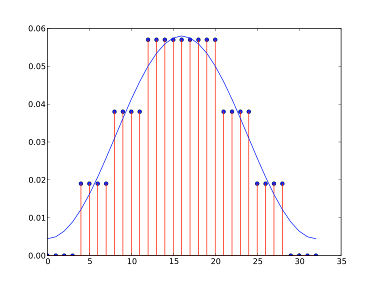
[Figure 1: Stepped Approximation of a LPF Impulse]

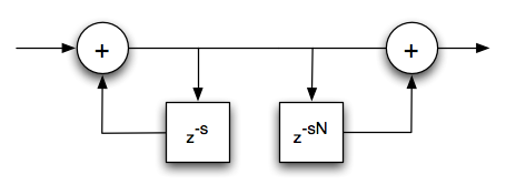
The original paper [1] introduced a method for the stepped-triangular approximation for a LPF impulse response.  And the resulting transfer function is as a cascade of recursive sums,

H(z) = H_{rrs}(z)H_{rss}(z)


The Hrrs(z) is the familiar recursive running sum,

H_{rrs}(z) = \frac{1-z^{-D}}{1-z^{-1}}

which has a flat impulse response,

 Impulse Response Recursive Running Sum

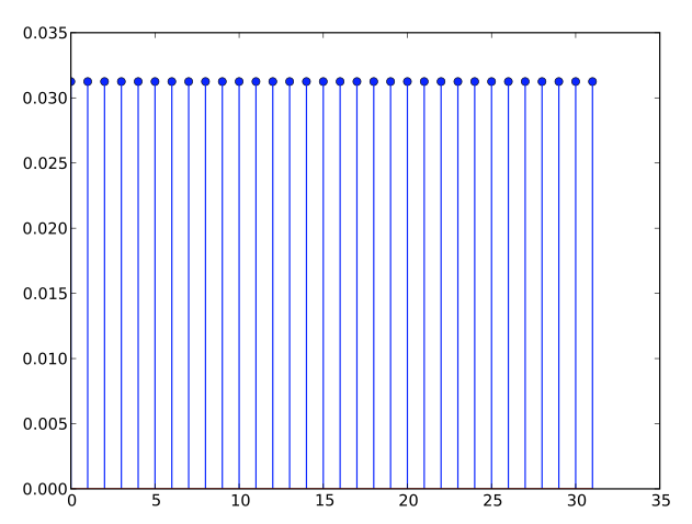
[Figure 2: Impulse Response Recursive Running Sum]

Hrss(z) is a recursive sparse sum where every s samples are used,

H_{rss}(z) = \frac{1 - z^{-sN}}{1 - z^{-s}}

 Impulse Response Recursive Sparse Sum

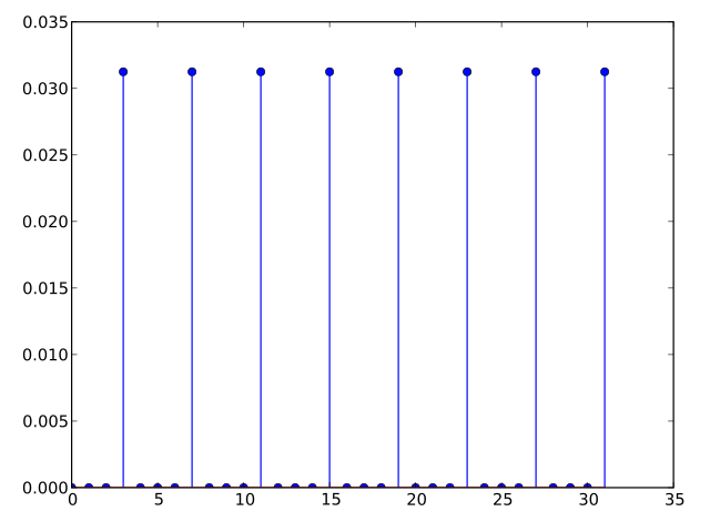
[Figure 3: Impulse Response Recursive Sparse Sum]


Both of the following can be implemented with an efficient recursive form that contains an integrator and difference combination.

To generate the stepped-triangular approximation, from a LPF impulse response, a simple rounding function g[n] is used,

 g[n] = r \cdot round \left ( \frac{h[n]}{r} \right )

The rounding function g[n] will quantize h[n] into one of three stepped-triangular approximation types.  Figures 1 and 4 show one such an example.  The three types determine the number of samples at the peak, less than s, equal to s, or greater than s, where s is the number of samples per step.

Frequency Response for an ST-Approximation

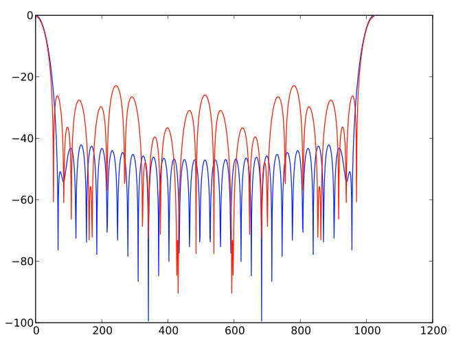
[Figure 4: Frequency Response for an ST-Approximation]

Figure 4 is an example of a ST-approximation frequency response.  I will leave it up to the reader to decide if this is a good approximation given the gains in computation efficiency.  The blue is the original frequency response and the red is the approximation using the stepped-triangual approach.


[1] Jovanovic-Dolecek, Gordana, Mitra, Sanjit, “Design of FIR Lowpass filters using stepped triangular approximation”


[ - ]
Comment by Rick LyonsAugust 10, 2011
Hi Chris, Thanks for pointing this filter design method out to us. It's certainly interesting. By the way, I found a downloadable copy (is "downloadable" a word?) of reference [1] at: http://www.ux.uis.no/norsig/norsig2002/Proceedings/papers/cr1018.pdf While quickly reviewing reference [1] I noticed: [I] One thing that initially puzzled me was that the authors wrote: "This paper presents a simple FIR lowpass filter design procedure which requires only one multiplication operation." The filter design procedure requires hundreds, or maybe thousands, of multiplies. What they should have written was: "This paper presents a simple FIR lowpass filter design procedure that yields a FIR filter requiring only one multiplication per output sample." [II] Also, I noticed that the variables 'N' and 'S' were defined in Section 2 of reference [1]. Then, sadly, their design example contradicted their own definitions of variables 'N' and 'S'. [II] The authors used the phrase "stepped triangular" to describe the designed filter's impulse response. I realized that the word triangular seems inappropriate. The designed filter's impulse response will only be triangular if the filter's transition region is fairly wide relative to the filter's sample rate. For filters with a narrow (sharp) transition region width the impulse response will not be triangular. OK, having said (griped about) all of this, I think the authors' filter design method is quite interesting and deserves our attention. I hope to experiment with their design idea as time allows. Thanks again, Chris, for alerting us to this FIR filter design technique. [-Rick-]
[ - ]
Comment by cfeltonAugust 11, 2011
Thanks for the comments. The referenced paper isn't the best quality, which is surprising since the co-author, Mitra, is the same Mitra that has published a DSP book? I orignally ran across the stepped-triangula in [2]. Then I found the reference above which I used for this brief blog post. I don't know if this is a decent method for approximating LPF and I see your point on the "stepped-triangular" name. My conclusion thus far has been no, it is not really a good method for approximating a LPF even with the computation gains. The part that I thought was interesting was the cascading of the, what I call, the sparse running sum.
H(z) = [1 - z^{sN}] / [1 - z^{-s}]
Where this is similar to the RRS but the integrator stage has an extra delay.
What this ends up doing is adding poles and canceling out some of the zeros. This can be observed in the blogs frequency response plots, where the Hrrs response each lobe is more attenuated and the Hrss has a "bump" in the higher frequencies. Because of this I haven't found a good use for Hrss. Now in [2] the author shows a better response using an additional term (1 + z^-R) / 2, this might be for a later post :). This is an example of the pole-zero plot with s=3 and N=5, and illustrates the canceling of the zeros in the higher frequencies.
(The poles, red x, are a little difficult to see on this plot) Also, after reading your comments I realize I had made a mistake in the blog post, how I intended to represent the variables. In general N is the number of steps and s is the number of samples per step, when trying to define the "stepped-triangular". And sN = D. I have made the corrections to the equations in this short blog post. I thought this could possibly be exploited in conjunction with the use of CIC filters. But I don't think it is as useful as my original thoughts. [2] Jovanovic-Dolecek, Gordana, "Modified CIC Filter for Rational Sample Rate Conversion", ECTI Transactions on Computer and Informatioin Technology Vol.4, No.1 May 2010 Chris
[ - ]
Comment by September 12, 2011
From the first glance, it looks like a first order Taylor approximation, which is like you said, an approximation with constant function.

To post reply to a comment, click on the 'reply' button attached to each comment. To post a new comment (not a reply to a comment) check out the 'Write a Comment' tab at the top of the comments.

Please login (on the right) if you already have an account on this platform.

Otherwise, please use this form to register (free) an join one of the largest online community for Electrical/Embedded/DSP/FPGA/ML engineers: