


Beat Notes: An Interesting Observation
Some weeks ago a friend of mine, a long time radio engineer as well as a piano player, called and asked me,
"When I travel in a DC-9 aircraft, and I sit back near the engines, I hear this fairly loud unpleasant whump whump whump whump sound. The frequency of that sound is, maybe, two cycles per second. I think that sound is a beat frequency because the DC-9's engines are turning at a slightly different number of revolutions per second. My question is, what sort of mechanism in the airplane could cause the audio from the two engines to be multiplied so that I can hear the low-frequency beat frequency?"

I didn't have an answer for my friend but his question did start me thinking.
Beat Notes
You've probably heard of beat notes before. In Mitra's terrific DSP book, he describes a beat note as follows [1]: If we multiply two sine wave signals, having similar frequencies, the result is a sum-frequency sine wave and a difference-frequency sine wave. Mathematically, this multiplication can be shown by a common trigonometric identity as:
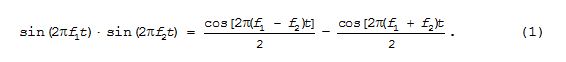
The cos[2π(f1–f2)t]/2 sinusoid, the difference frequency, is called the "beat note." If you've ever studied AM demodulation then you've seen that sum and difference Eq. (1) before.
I remember years ago when someone showed me how to tune a guitar string to the proper pitch, relative to another string, using the notion of beat notes. When you pluck two strings tuned to similar, but not identical, frequencies you can hear what seems to be a low-frequency beat note. When the two strings are tuned closer and closer in frequency the beat note becomes lower in frequency. When the two strings are tuned to the same frequency (same pitch) the beat note frequency goes to zero and can no longer be heard. In that event the two strings are properly tuned relative to each other. As was explained to me, the beat note we hear is the difference in frequency between two improperly tuned strings. What I've since learned is this description of a guitar's audible beat note is NOT correct. Allow me to explain.
The Product and Sum of Two Audio Tones
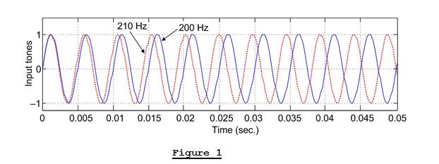
Figure 1 shows two sine wave tones, an f1 = 210 Hz tone and an f2 = 200 Hz tone.
If we multiply those two Figure 1 sine waves, as indicated by Eq. (1), the product is shown as the solid curve in Figure 2. In that figure we see the solid curve is the sum-frequency (f1 + f2) 410 Hz sine wave. And the amplitude offset (the instantaneous bias) of the 410 Hz sine wave fluctuates at a rate of a 10 Hz difference frequency (f1 - f2) as shown by the red dashed curve. I've included the red dashed curve in Figure 2 for reference only. Again, the blue curve alone is our sin(2π210t)•sin(2π200t) product signal
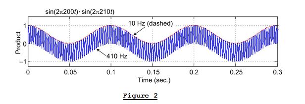
If we were to drive a speaker with the Figure 2 product signal we'd hear the 410 Hz sum-frequency tone but we would NOT hear the 10 Hz amplitude offset. (Matlab code is provided below to demonstrate what I'm claiming here.)
As it turns out, Eq. (1) is not the expression we need when considering the sum of two sine wave tones. It's on the following trigonometric identity that we should focus:
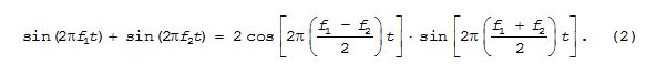
Equation (2), the sum of a sin(2πf1t) sine wave and a sin(2πf2t) sine wave, describes what happens when two guitar strings are plucked as well as what my friend hears inside a DC-9 aircraft.
If we add the two Figure 1 sine waves, as indicated by Eq. (2), the sum is shown as the solid blue curve in Figure 3. In that figure we see the solid curve is the sin[2π(200+210)t/2] 205 Hz tone predicted by Eq. (2).
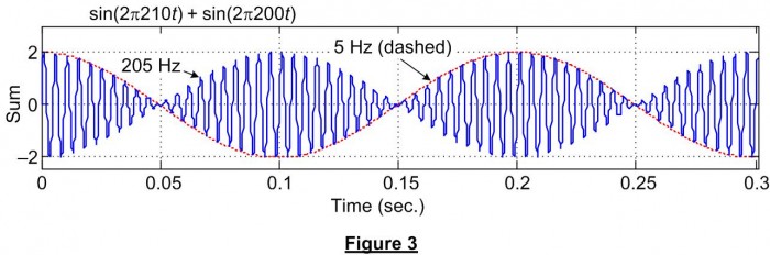
However, the peak-to-peak amplitude of that 205 Hz tone is modulated (multiplied) by a cos[2π(210-200)t/2] 5 Hz sinusoid. (I've included the red dashed curve in Figure 3 for reference only.) Isn't it interesting that when we add a 210 Hz sine wave to a 200 Hz sine wave the result is a fluctuating-amplitude 205 Hz sinusoidal wave? I don't think that fact is at all intuitive. At least it wasn't intuitive to me. That sine wave summation behavior is the "interesting observation" mentioned in the title of this blog.
In Eq. (2), with f1 = 210 and f2 = 200, I view the factor 2cos(2π5t) in Eq. (2) as an amplitude function that controls the amplitude of the sin(2π205t) audio tone. That viewpoint is shown below.
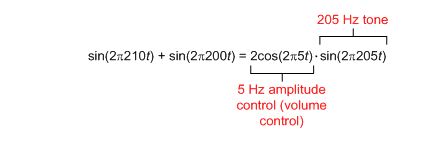
Now if we drive a speaker with the Figure 3 sum signal we'd hear a 205 Hz tone and that tone's amplitude (volume) would fluctuate at a rate of 10 Hz. The amplitude fluctuations occur at a 10 Hz rate because the 205 Hz tone's amplitude goes from zero to its maximum value once for each half cycle of the 5 Hz modulating frequency. (Again, Matlab code to generate and listen to the Figure 3 signal is given below.)
Conclusion
So what this all means is that when we simultaneously pluck two guitar strings tuned to 210 Hz and 200 Hz respectively, we hear a tone whose frequency is 205 Hz (the average of 210 Hz and 200 Hz) and we also hear the 205 Hz tone's amplitude fluctuate at a 10 Hz rate. And the oscillating amplitude fluctuations give us the impression that we hear a 10 Hz tone when in fact no 10 Hz tone exists in the Figure 3 sum signal. I say that because the spectrum of the Figure 3 solid sum-signal curve contains two spectral components, a 200 Hz tone and a 210 Hz tone. Nothing more and nothing less. As such we can say that plucking two guitar strings, off-tuned by 10 Hz, does NOT generate a sinusoidal 10 Hz audio beat note.
And to answer the DC-9 question, in my opinion no multiplication of engine noise is taking place. The audible whump whump whump sound is fluctuations in the amplitude (volume) of the two engines' average rotational frequencies.

References
[1] S. Mitra, Digital Signal Processing, A computer-Based Approach, McGraw-Hill, New York, New York, 2011, pp. 70-71.
Matlab Code
The following Matlab code enables you to generate, and listen to, the sum of two audio tones.
%     Filename:  Beat_Frequency.m
%
%     [Richard Lyons, Feb. 2013]

clear, clc

Fs = 8192; % Sample rate of dig. samples
N = 8192;  % Number of time samples
n = 0:N-1;

Wave_1 = sin(2*pi*210*n/Fs);  % First tone, 210 Hz
Wave_2 = sin(2*pi*200*n/Fs);  % Second tone, 200 Hz

        % Plot the two tones
        figure(1)
        plot(n/Fs, Wave_1, '-b')
        ylabel('200 Hz'); xlabel('Time (sec.)');
        hold on
        plot(n/Fs, Wave_2, '-r')
        axis([0, 0.05, -1.2, 1.5]);
        ylabel('Input tones'); xlabel('Time (sec.)');
        title('red = 200 Hz tone,  blue = 210 Hz tone');
        grid on, zoom on
        hold off

Product = Wave_1.*Wave_2;
Sum = Wave_1 + Wave_2;

        % Plot the tones' product and sum
        figure(2)
        subplot(2,1,1)
        plot(n/Fs, Product, '-b'),
        ylabel('Product'); xlabel('Time (sec.)');
        grid on, zoom on
        hold on
        Red_Curve = 0.5*cos(2*pi*10*n/Fs) + 0.5;  % Used for plotting only
        plot(n/Fs, Red_Curve, '-r')
        axis([0, 0.3, -1.25, 1.5]);
        hold off
        grid on, zoom on

        subplot(2,1,2)
        plot(n/Fs, Sum, '-b')
        hold on
        Red_Curve = 2*cos(2*pi*5*n/Fs);  % Used for plotting only
        plot(n/Fs, Red_Curve, '-r')
        axis([0, 0.3, -2.4, 3]);
        hold off
        ylabel('Sum'); xlabel('Time (sec.)');
        grid on, zoom on

% Play all the signals
    sound(Wave_1, Fs)
    pause(1.2)
    sound(Wave_2, Fs)
    pause(1.2)
    sound(Product, Fs)
    pause(1.2)
    sound(Sum, Fs)

% Spec analysis of the "Sum" signal
Spec = fft(Sum);
Spec_Mag = abs(Spec);
Freq = n*Fs/N; % Freq vector in Hz

        figure (3)  % Plot positive-freq spec amg
        plot(Freq(1:N/16), Spec_Mag(1:N/16))
        title('Spec Mag of "Sum" signal')
        ylabel('Mag.'), xlabel('Hz')
        grid on, zoom on
- Comments
- Write a Comment Select to add a comment

Ah, ...that's an interesting thought. Thanks.
By any chance would your first name be Brian?
[-Rick-]
How do you know the brain perceives sound in a frequency/time domain?
Do all brains work in such a way or only outstanding ones?
All brains work that way. In the most basic terms it's the difference between rhythm and pitch. There are a number of different models to explain how the brain perceives pitch, all of which are interesting and hard to understand (IMO). Based on my experience, I like to think of the ear as containing a number of band pass filters. Each filter can only resolve a single frequency. So if a signal that falls in a filter is AMed at a frequency lower than half the bandwidth of the filter, you hear a single pitch varying in amplitued. If the signal is modulated at frequencies higher than half the bandwidth, the signal is spread into adjacent filters and you hear two pitches.
Where it gets weird (and I highly recommend you all try this at home, because it's super fun), is what happens between going from a single amplitude varying pitch to two distinct pitches. Take a sine wave at 1kHz for example and modulate it with a sine wave that you can set between .1Hz and 500 Hz. At low frequencies, you'll hear a single pitch. At high frequencies you'll hear two. However, there are intermediate frequencies where you'll be able to hear three distinct pitches.
As Rick noted, the frequency spectrum of this signal always contains two distinct pitches, no more no less. This simple experiment shows that thinking of audio in terms of the frequency spectrum alone will only go so far to represent perception of sound.
-Dan
thank you very much for your lines.
I wasn't aware that we bring into confusion two absolutely different physical processes when we refer to the "beat frequency" when talking about audio reception and when using the same term "beat frequency" when talking about the mixing product with a "beat frequency oscillator".
After reading your notes on the topic, everything is pretty clear! We just have to learn to talk precisely - maybe the more difficult challenge. ;)"
Sabine
Aren't equations (1) and (2) essentially the same phenomenon, just switched around?
In acoustics - i.e. when tuning a guitar or perhaps sitting in the back of a DC9 - the waveforms of two closely-spaced frequencies are summed, and we hear a (low) difference tone modulated, i.e. multiplied, by a (high) sum or average tone. See (2).
In an RF receiver, the phenomenon is exploited in the reverse direction. We modulate (or mix) local oscillator tuned closely to the carrier frequency of the incoming waveform, so that we get a low-frequency difference term which we can digitize and analyse using a relatively low bandwidth A2D converter, while ignoring the high-frequency sum term. See (1).
Do I need an account, to post here?? Just checking...
-RFH
To post reply to a comment, click on the 'reply' button attached to each comment. To post a new comment (not a reply to a comment) check out the 'Write a Comment' tab at the top of the comments.
Please login (on the right) if you already have an account on this platform.
Otherwise, please use this form to register (free) an join one of the largest online community for Electrical/Embedded/DSP/FPGA/ML engineers:


