


Is Linear Phase Really Ideal for Audio?
It is generally accepted that zero or linear phase filters are ideal for audio applications. This is because such filters delay all frequencies by the same amount, thereby maximally preserving waveshape. Mathematically, all Fourier-components passed by the filter remain time-synchronized exactly as they were in the original signal. However, this section will argue that a phase response somewhere between linear- and minimum-phase may be even better in some cases. We show this by means of a Matlab experiment comparing minimum-phase and zero-phase impulse responses.
The matlab code is shown in Fig.11.1. An order ![]() elliptic-function lowpass filter [64] is designed
with a cut-off frequency at 2 kHz. We choose an elliptic-function
filter because it has a highly nonlinear phase response near its
cut-off frequency, resulting in extra delay there which can be
perceived as ``ringing'' at that frequency. The cut-off is chosen at
2kHz because this is a highly audible frequency. We want to clearly
hear the ringing in this experiment in order to compare the zero-phase
and minimum-phase cases.
elliptic-function lowpass filter [64] is designed
with a cut-off frequency at 2 kHz. We choose an elliptic-function
filter because it has a highly nonlinear phase response near its
cut-off frequency, resulting in extra delay there which can be
perceived as ``ringing'' at that frequency. The cut-off is chosen at
2kHz because this is a highly audible frequency. We want to clearly
hear the ringing in this experiment in order to compare the zero-phase
and minimum-phase cases.
% ellipt.m - Compare minimum-phase and zero-phase % lowpass impulse responses. dosounds = 1; N = 8; % filter order Rp = 0.5; % passband ripple (dB) Rs = 60; % stopband ripple (-dB) Fs = 8192; % default sampling rate (Windows Matlab) Fp = 2000; % passband end Fc = 2200; % stopband begins [gives order 8] Ns = 4096; % number of samples in impulse responses [B,A] = nellip(Rp, Rs, Fp/(0.5*Fs), Fc/(0.5*Fs)); % Octave % [B,A] = ellip(N, Rp, Rs, Fp/(0.5*Fs)); % Matlab % Minimum phase case: imp = [1,zeros(1,Ns/2-1)]; % or 'h1=impz(B,A,Ns/2-1)' h1 = filter(B,A,imp); % min-phase impulse response hmp = filter(B,A,[h1,zeros(1,Ns/2)]); % apply twice % Zero phase case: h1r = fliplr(h1); % maximum-phase impulse response hzp = filter(B,A,[h1r,zeros(1,Ns/2)]); % min*max=zp % hzp = fliplr(hzp); % not needed here since symmetric elliptplots; % plot impulse- and amplitude-responses % Let's hear them! while(dosounds) sound(hmp,Fs); pause(0.5); sound(hzp,Fs); pause(1); end |
Let the impulse response of the ![]() th order lowpass filter be denoted
th order lowpass filter be denoted
![]() . It is neither minimum nor maximum phase because there are
zeros on the unit circle. (An elliptic-function filter has all of its
zeros on the unit circle.) However, nothing of practical
importance changes if we move the zeros from radius 1 to radius
. It is neither minimum nor maximum phase because there are
zeros on the unit circle. (An elliptic-function filter has all of its
zeros on the unit circle.) However, nothing of practical
importance changes if we move the zeros from radius 1 to radius
![]() , say, which would give a minimum-phase perturbation of
the elliptic lowpass.
, say, which would give a minimum-phase perturbation of
the elliptic lowpass.
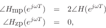
From ![]() we prepare two impulse responses having the same
magnitude spectra but different phase spectra:
we prepare two impulse responses having the same
magnitude spectra but different phase spectra:
again as discussed in §10.6.
Since we are listening to a lowpass-filtered impulse, it is reasonable
to define the ideal expected sound as a ``lowpass-filtered click,'' or
some kind of ``compact thump.'' We may therefore ask which signal
sounds more like a lowpassed click,
![]() or
or
![]() ? In the
minimum-phase case, all filter ringing occurs after the main pulse,
while in the zero-phase case, it is equally divided before and after
the main pulse (see Fig.11.2). Listening tests confirm that the
``pre-ring'' of the zero-phase case is audible before the main click,
giving it a kind of ``chirp'' quality. Most listeners would say the
minimum-phase case is a better ``click''. Since forward masking is
stronger than backward masking in hearing perception, the optimal
distribution of ringing is arguably a small amount before the main
pulse (however much is inaudible due to backward masking, for
example), with the rest occurring after the main pulse.
? In the
minimum-phase case, all filter ringing occurs after the main pulse,
while in the zero-phase case, it is equally divided before and after
the main pulse (see Fig.11.2). Listening tests confirm that the
``pre-ring'' of the zero-phase case is audible before the main click,
giving it a kind of ``chirp'' quality. Most listeners would say the
minimum-phase case is a better ``click''. Since forward masking is
stronger than backward masking in hearing perception, the optimal
distribution of ringing is arguably a small amount before the main
pulse (however much is inaudible due to backward masking, for
example), with the rest occurring after the main pulse.
![\includegraphics[width=\twidth]{eps/elliptt}](http://www.dsprelated.com/josimages_new/filters/img1286.png) |
Figure 11.3 verifies that the magnitude spectra are the same in each case.
![\includegraphics[width=\twidth]{eps/elliptf}](http://www.dsprelated.com/josimages_new/filters/img1287.png) |
Next Section:
Creating Minimum Phase Filters and Signals
Previous Section:
Minimum-Phase/Allpass Decomposition


