


Plane-Wave Scattering
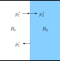
Consider a plane wave with peak pressure amplitude ![]() propagating
from wave impedance
propagating
from wave impedance ![]() into a new wave impedance
into a new wave impedance ![]() , as shown in
Fig.C.15. (Assume
, as shown in
Fig.C.15. (Assume ![]() and
and ![]() are real and positive.)
The physical constraints on the wave are that
are real and positive.)
The physical constraints on the wave are that
- pressure must be continuous everywhere, and
- velocity in must equal velocity out (the junction has no state).
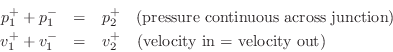
As derived in §C.7.3, we also have the Ohm's law relations:

To obey the physical constraints at the impedance discontinuity, the
incident plane-wave must split into a reflected plane wave
![]() and a transmitted plane-wave
and a transmitted plane-wave ![]() such that
pressure is continuous and signal power is conserved. The physical
pressure on the left of the junction is
such that
pressure is continuous and signal power is conserved. The physical
pressure on the left of the junction is
![]() , and the
physical pressure on the right of the junction is
, and the
physical pressure on the right of the junction is
![]() , since
, since ![]() according to our set-up.
according to our set-up.
Scattering Solution
Define the junction pressure ![]() and junction velocity
and junction velocity ![]() by
by
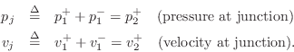
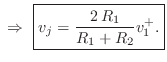
Then we can write
![\begin{eqnarray*}
p^+_1+p^-_1 &=& p^+_2\;=\;p_j\\ [10pt]
\,\,\Rightarrow\,\,R_1v...
...\\ [10pt]
\,\,\Rightarrow\,\,2\,R_1v^{+}_1 - R_1 v_j &=& R_2 v_j
\end{eqnarray*}](http://www.dsprelated.com/josimages_new/pasp/img3532.png)
![$\displaystyle v^{-}_1 = v_j - v^{+}_1 = \left[\frac{2\,R_1}{R_1+R_2} - 1\right]v^{+}_1 = \frac{R_1-R_2}{R_1+R_2} v^{+}_1.
$](http://www.dsprelated.com/josimages_new/pasp/img3536.png)
Using the Ohm's law relations, the pressure waves follow easily:
![\begin{eqnarray*}
p^+_2 &=& R_2v^{+}_2 = R_2 v_j = \frac{2\,R_2}{R_1+R_2}p^+_1\\ [10pt]
p^-_1 &=& -R_1v^{-}_1 = \frac{R_2-R_1}{R_1+R_2} p^+_1
\end{eqnarray*}](http://www.dsprelated.com/josimages_new/pasp/img3537.png)
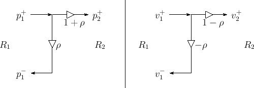
Reflection Coefficient
Define the reflection coefficient of the scattering junction as

![\begin{eqnarray*}
p^+_2 &=& (1+\rho)p^+_1\\ [3pt]
p^-_1 &=& \rho\,p^+_1
\end{eqnarray*}](http://www.dsprelated.com/josimages_new/pasp/img3539.png)
Signal flow graphs for pressure and velocity are given in Fig.C.16.
 |
It is a simple exercise to verify that signal power is conserved by
checking that
![]() .
(Left-going power is negated to account for its opposite
direction-of-travel.)
.
(Left-going power is negated to account for its opposite
direction-of-travel.)
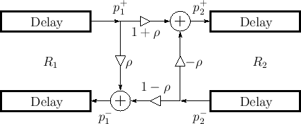
So far we have only considered a plane wave incident on the left of
the junction. Consider now a plane wave incident from the right. For
that wave, the impedance steps from ![]() to
to ![]() , so the reflection
coefficient it ``sees'' is
, so the reflection
coefficient it ``sees'' is ![]() . By superposition, the signal flow
graph for plane waves incident from either side is given by
Fig.C.17. Note that the transmission coefficient is
one plus the reflection coefficient in either direction. This signal
flow graph is often called the ``Kelly-Lochbaum'' scattering junction
[297].
. By superposition, the signal flow
graph for plane waves incident from either side is given by
Fig.C.17. Note that the transmission coefficient is
one plus the reflection coefficient in either direction. This signal
flow graph is often called the ``Kelly-Lochbaum'' scattering junction
[297].
 |
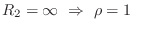
There are some simple special cases:
-
 (e.g., rigid wall reflection)
-
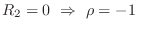 (e.g., open-ended tube)
-
 (no reflection)
Next Section:
Plane-Wave Scattering at an Angle
Previous Section:
Total Energy in a Rigidly Terminated String


