


A Wide-Notch Comb Filter
This blog describes a linear-phase comb filter having wider stopband notches than a traditional comb filter.
Background
Let's first review the behavior of a traditional comb filter. Figure 1(a) shows a traditional comb filter comprising two cascaded recursive running sum (RRS) comb filters. Figure 1(b) shows the filter's co-located dual poles and dual zeros on the z-plane, while Figure 1(c) shows the filter's positive-frequency magnitude response when, for example, D = 9. The stopband notches (nulls) are located at integer multiples of fs/D Hz where fs is the input signal sample rate measured in Hz.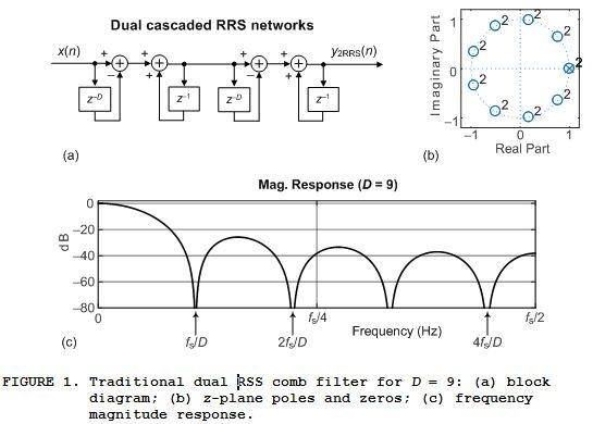
In what follows we show a comb filter having wider stopband notches than are shown in Figure 1(c).
The Wide-Notch Comb Filter
The Figure 1(a) dual RRS network has a triangular time-domain impulse response. I have discovered that if we build a network whose impulse response is that of the dual RRS network but with a reduced-amplitude center sample then we'll have a wide-notch comb filter.
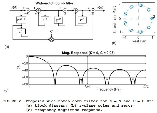
As described in Appendix A, the z-domain transfer function of the proposed wide-notch comb filter is:

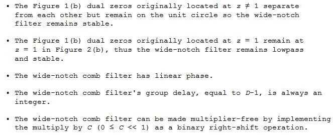
Figure 2(a)'s feedforward signal path using coefficient C imparts the four following favorable characteristics to the wide-notch filter:
The filter's frequency-domain notch width and the peak of the mini-sidelobes within the notches depend on both the delay line length D and the C coefficient. In most comb filter applications variable D is a fixed value, so coefficient C becomes the primary control variable to influence the filter's notch characteristics.
Values in the range 0.01 ≤ C ≤ 0.1 are reasonable for coefficient C to start any software modeling of the wide-notch comb filter. What you will find is that when you double the value of the C coefficient the peak of the mini-sidelobes within the notches increases by roughly six dB.
The wide-notch comb filter has a high low-frequency gain, just as do cascaded integrator-comb filters (CIC) filters. So to avoid register overflow the filter should be implemented using two's complement arithmetic for the reasons described in Reference [2].A Unity-Gain Wide-Notch Comb Filter
The lowpass gain (gain at zero Hz) of the Figure 2(a) wide-notch comb filter is:
gain = D2—C. (2)
Appendix B shows how to implement a unity-gain wide-notch comb filter.
When to Use the Wide-Notch Comb Filter
The wide-notch comb filter can be useful in reducing the computational workload of interpolated finite-impulse response filters [1,2] and specialized narrowband lowpass IIR filters [3,4], as well as reducing the aliasing error caused by sample rate change in even-ordered cascaded integrator-comb filters (CIC) filters [5]. Another potential application of a wide-notch comb filter is its use as a comb filter for attenuating noise contamination from AC power line harmonics.
Conclusion
I've discussed the development and performance of the wide-notch comb filter in Figure 2(a) that may prove beneficial in applications that have previously used traditional recursive running sum (RRS) comb filters. In addition, Appendix B shows how to implement a unity passband gain wide-notch comb filter.
References
[1] G. Dolecek, and V. Dolecek, "Multistage Digital Filter", 13th International Research/Expert Conference, Hammamet, Tunisia, Oct. 2009, Available online: http://www.tmt.unze.ba/zbornik/TMT2009/096-TMT09-147.pdf
[2] R. Lyons, "Understanding cascaded integrator-comb filters", Available online: https://www.embedded.com/understanding-cascaded-integrator-comb-filters/
[3] R. Lyons, "Improved Narrowband Lowpass IIR Filters in Fixed-Point Systems". IEEE Signal Processing Magazine. March, 2009. Available online: https://www.researchgate.net/publication/224397424_Improved_narrowband_low-pass_IIR_filters_in_fixed-point_systems_DSP_Tips_Tricks
[4] F. Harris and W. Lowdermilk, "Implementing Recursive Filters with Large Ratio of Sample Rate to Bandwidth", in Conference Record of the Forty-First Asilomar Conference on Signals, Systems and Computers, Pacific Grove, CA, Nov. 4–7, 2007, pp. 1149–1153. Available online: https://d23s79tivgl8me.cloudfront.net/user/124841/narrowband%20iir%20filters_2_40945.pdf
[5] R. Lyons, "Turbocharging Interpolated FIR Filters", IEEE Signal Processing Magazine, Vol. 24, No. 5, Sept. 2007. Available online: https://www.researchgate.net/publication/277702593_Turbocharging_Interpolated_FIR_Filters
[6] R. Lyons, "Controlling a DSP Network's Gain: A Note For DSP Beginners", available online at: https://www.dsprelated.com/showarticle/1249.php
Appendix A: Derivation of Eq. (1)
The derivation of this blog's Eq. (1) is described as follows: The foundation of the proposed wide-notch comb filter is two cascaded Recursive Running Sum filters as shown in Figure A-1(a).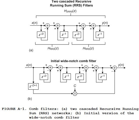
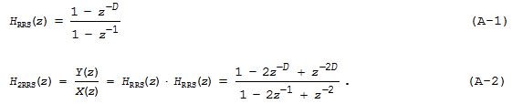
The z-domain transfer functions of a single RRS network and the cascaded Figure A-1(a) network are given in the following two equations:
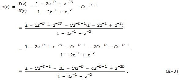
We can eliminate one of Figure A-1(b)'s long delay lines using the proposed network given in this blog's Figure 2(a) whose z-domain transfer function is also given by Eq. (A-3).
Appendix B
To implement a unity passband (at zero Hz) gain wide-notch comb filter we must reduce the Figure 2(a) filter's gain by a factor of D2‑C. The simplest method to do this is shown in Figure B-1(a). There we merely scaled the filter's output sequence by the reciprocal of the Figure 2(a) filter's passband gain of D2‑C.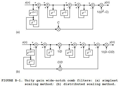
In fixed-point implementations, to reduce the necessary word width of the 3rd and 4th accumulators (3rd and 4th adders) and the z‑D delay line, the distributed scaling method in Figure B-1(b) can be used. Equation (B-1) gives the transfer function for both filters in Figure B-1:

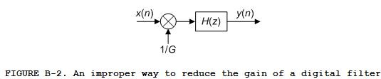
Such a gain reduction method is a bad idea for the reasons discussed in Reference [6].
- Comments
- Write a Comment Select to add a comment
Dear Rick,
I implemented your design in ASN filterScript, see here for the video: Wide band notch filiter video
Very nice idea indeed!
Regards,
Sanjeev
Here's the filterscript code if you want to try it youself:
// Description: The Wide-Notch Comb Filter
// Author: Rick lyons
// Date: Monday, 25 November 2019
// Comments:
//
ClearH1; // clear primary filter from cascade
interface D = {2,20,1,9}; // interface variable definition
interface C = {0, 0.5,0.01,0.05};
Main() // main loop
// 1 - Cz^-(D-1) -2(1-C)z^-D + z^-2D
// H(z) = ----------------------------------
// 1 - 2z^-1 + z^-2
Num = {1, zeros(D-2), -C, -2*(1-C), -C, zeros(2*D-(D+2)),1}; // define numerator coefficients
Den = {1,-2,1}; // define denominator coefficients
Gain = 1/(D^2-C); // define gain

Hi.
My my, what a great video. Good job Sanjeev. You are a filter maestro!
Hi Sanjeev.
Your video is a nice demonstration of the power of your ASN Filter Design software.
Thanks, Rick! As I mentioned, I was really impressed by your idea, and look forward to seeing more filters along simular lines.
I assume that you still have a licenced version of the ASNFD? As it makes experimenation much more easier....
with kind regards,
Sanjeev.
Hello Rick,
first of all thank you for sharing with us the wide-notch comb filter. I have two questions:
1) have you compared the passband behavior of the proposed wide-notch comb filter with the traditional dual cascaded RRS filter? (cutoff frequency / attenuation)
2) How difficult would it be to increase the "order" of the wide-nocht comb filter? Right now it is based on a dual cacaded RRS filter and lets imagine one is interested in in a third order RRS?
Hi hirnprinz.
1) Yes, I sure did. I created the following drawing but chose not to include it in my blog.

2) Your notion of increasing the order of the wide-notch comb is an interesting idea. An idea I didn't explore. Off the top of my head my guess is that three cascaded RRS sections couldn't be made to work properly, but four cascaded RRS section might prove to be interesting. I'll look into your interesting idea.
hirnprinz, your second question is one of those wonderful "What happens if ..." questions. ("What happens if we increase the order of the wide-notch comb filter?") Such "What happens if ..." questions often lead to discoveries!!
Hi Rick,
thanks for the additional figures. I really like your idea more and more ...
Looking forward to see where the journey of this "what happens if" question will take you!
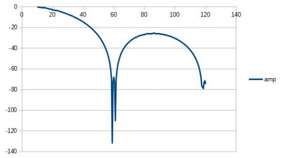
Dear Rick,
Here's a comparsion of your WB filter (C=0.1, D=10) vs the standard NB comb for a 50Hz harmonics attenuation case:
Standard comb (group delay: 2.5 samples)

WB comb (group delay: 9 samples)

As seen, there's about a 30dB improvement around 50Hz! The WB filter a larger group delay. However, what I really like, is that we can still get 60dB attentuation around the harmonics even when the powerline flucuates, i.e. 50Hz ± 1%
with kind regards,
Sanjeev.
Mr T is wrong sometimes.
Hi nori.
Ha ha. No, Mr. T is not wrong. It's my fault. I drew the Figure 1(a) standard exponential averager the same way it's typically shown in the literature of DSP. I should have drawn it with the 'multiply-by-alpha' operation at the y(n) output, rather than at the x(n) input. nori, thanks for pointing that out to me.
Hi Sanjeev.
I agree with your interesting observations.
Your first spectral magnitude plot puzzled me at first. But now I think it's the freq magnitude plot for a simple delay-line comb filter with no integrator (no accumulator). I think your delay-line comb's impulse response is:
h(k) = [1, 0, 0, 0, 0, -1]
and the sample rate is 250 samples/second.
So can I implement a CIC filter with a parallel D-1 delay (and summer) to do wide-notch filtering and decimation?
I typically sample much faster than needed, do a simple low pass, but then need to get rid of power line noise in my filtered (ecg or eeg) data.
Hi forthprgrmr. I don't understand what your words "parallel D-1 delay (and summer)" mean. Can you give me a block diagram of the filter you have in mind?
Sorry for the confusion.
See your figure B-1 (a).
The top looks like a CIC filter. Is there any advantage if I'm doing decimation along with trying to make a wide notch?
Hi forthprgrmr. Oh shoot. You've asked such a good question! And I don't have an answer for you off the top of my head. You're right. Figure B-1(a) is a second-order CIC filter, but with a feedforward signal path. I think your question is: "Can we implement a wide-notch 2nd-order decimating filter as shown below:"

Sadly I've never studied, or analyzed, the behavior of the above network, so I'm unable to answer your question. When I have time I hope to investigate the above filter in more detail.
The filter I drew in my Dec. 20 Comment is not going to work. And it was silly of me to even think it might work. I think the only chance you have of implementing a decimating wide-notch comb filter is start with the filter in my blog's Figure A-1(b), and see if you can insert a downsampling operation right after the first integrator and insert a downsampling operation in the feedforward path.
 Hi Rick,
Here is a plot of my implementation of your wide notch filter. Actual code running on a small MSP430 (16bit) system.
This system runs at 1200Hz data collection, and does decimation by 10 to 120Hz output rate.
This is done with a two stage CIC filter with R=10, D=20, and N=2.
The "extra" path added to the output is done with a three point software delay line, carefully moving data from point 0 to point -9 to point -19 before adding (I'm using a negative value for C). But only 3 points to the extra delay line are needed making memory usage low.
Obviously this works well. The computational load is very low.
The point of this is to get bio signals (eeg, ecg, pulse, etc) filtered where the power line
might not be exactly 60Hz, or the micro's sampling might not be exactly 1200Hz. Sampling accuracy is often set in an on-board oscillator that doesn't have high accuracy or stability. A wide notch is welcome.
Thanks!
Gary
I was unable to to implement a decimating CIC filter using my Figure 2(a) network when my delay length D was equal to the decimation factor R. But it appears you were successful when you set R=10 and D=20.
I'd like to learn the details of your decimating CIC filter. forthprgrmr, would you please send me a private e-mail at: R.Lyons@ieee.org
To post reply to a comment, click on the 'reply' button attached to each comment. To post a new comment (not a reply to a comment) check out the 'Write a Comment' tab at the top of the comments.
Please login (on the right) if you already have an account on this platform.
Otherwise, please use this form to register (free) an join one of the largest online community for Electrical/Embedded/DSP/FPGA/ML engineers:


