


A New Contender in the Quadrature Oscillator Race
This blog advocates a relatively new and interesting quadrature oscillator developed by A. David Levine in 2009 and independently by Martin Vicanek in 2015 [1]. That oscillator is shown in Figure 1.
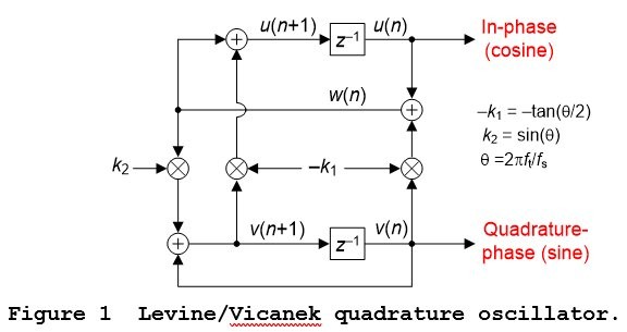
The time domain equations describing the Figure 1 oscillator are
w(n) = u(n)-k1v(n). (1)
u(n+1) = w(n)-k1v(n+1). (2)
v(n+1) = v(n) + k2w(n). (3)
The coefficients k1 and k2 are
k1 = tan($\theta$/2), (4a)
k2 = sin($\theta$), (4b)
and
$\theta$ = 2$\pi$ft/fs radians, (4c)
where ft is the oscillator’s tuned frequency (in Hz) and fs is the data sample rate (in Hz).
The Merits of the Levine/Vicanek Oscillator
Relative to the two traditional quadrature oscillators described in Appendix A the Levine/Vicanek oscillator has several advantageous properties. The oscillator:
• Has good tuned frequency accuracy at low frequencies,
• Its computational workload is reasonable, and
• It is a guaranteed stable oscillator.
Oscillator Implementation
In software the Figure 1 Levine/Vicanek oscillator is implemented by
Step# 1: Defining coefficients k1 and k2,
Step# 2: For n = 0 set the two outputs to u(0) = 1 and v(0) = 0.
Step# 3: Using v(0) and u(0) compute w(1),
Step# 4: Using v(0) and w(1) compute v(1),
Step# 5: Using w(1) and v(1) compute u(1),
Step# 6: Using v(1) and u(1) compute w(2),
Step# 7: Using v(1) and w(2) compute v(2),
Step# 8: Using w(2) and v(2) compute u(2),
and so on.
Additional Information
To add to the material provided here and in Reference [1], the PDF file associated with this blog provides additional information. That file’s Appendix B derives the transfer functions of the Levine/Vicanek quadrature oscillator and its Appendix C provides an algebraic proof of the oscillator’s guaranteed stability.
Conclusion
This blog publicized the beneficial properties of the Levine/Vicanek quadrature oscillator. That oscillator’s straightforward implementation and guaranteed stability make it a useful candidate for applications requiring a quadrature oscillator.
Postscript
Vicanek developed his quadrature oscillator in 2015. After I initially wrote this blog I learned that A. David Levine (inventor, musician, and musical technologist extraordinaire) developed a quadrature oscillator mathematically equivalent to Vicanek’s in 2009. Levine, a DSP engineer who actually knows which end of a soldering iron is hot, used his oscillator in a commercial hardware product described at the following website: https://muzemazer.com/mmcv

References
[1] M. Vicanek, “A New Recursive Quadrature Oscillator”,
October, 2015, Available online at:
https://www.vicanek.de/articles.htm
[2] Frerking, M., Digital Signal Processing in Communications Systems,
Chapman & Hall, 1994, pp. 214-217.
[3] R. Lyons, Understanding Digital Signal Processing,
3rd Ed., Prentice Hall, Englewood Cliffs, New Jersey, 2011,
pp. 834-835.
[4] C. M. Rader and B. Gold, “Effects of Parameter Quantization on the
Poles of Digital a Filter”, Proceedings of the IEEE, Vol. 55,
May 1967, pp. 688-689.
[5] S. Mitra, "Digital Signal Processing", 4th Edition, McGraw Hill
Publishing, 2011, pp. 674-675.
[6] J. Proakis and D. Manolakis, Digital Signal Processing-
Principles, Algorithms, and Applications, 3rd Ed., Prentice
Hall, Upper Saddle River, New Jersey, 1996, pp. 574–576.
[7] A. Oppenheim and R. Schafer, Discrete-Time Signal Processing,
2nd Ed., Prentice Hall, Englewood Cliffs, New Jersey, 1999,
pp. 382–384.
[8] C. Turner, “Recursive Discrete-Time Sinusoidal Oscillators”,
Available online at: http://claysturner.com/
[9] R. Lyons, Understanding Digital Signal Processing,
3rd Ed., Prentice Hall, Englewood Cliffs, New Jersey, 2011,
pp. 786-789.
Appendix A: Two Common 2nd-Order Quadrature Oscillators
To help us appreciate the novel Vicanek quadrature oscillator this appendix gives a brief description of the properties of two traditional quadrature oscillators that have been previously presented in the literature of DSP.
Those two well-known quadrature oscillators, based on 2nd-order resonators, are shown in Figure A-1.
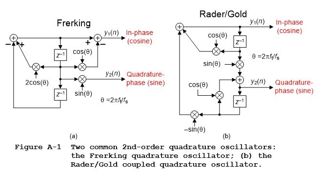
The Frerking oscillator in Figure A-1(a) is based upon the well-known 2nd-order IIR resonator that’s described in Reference [2]. While its outputs are guaranteed stable (the oscillator’s z-domain poles always lie on the z-plane’s unit circle) this oscillator’s tuned frequency accuracy depends on the tuned frequency—and that accuracy is poor at low frequencies.
The Rader/Gold oscillator in Figure A-1(b) is based upon the so called “coupled” 2nd-order IIR resonator so thoroughly covered in the literature of DSP [3‑7]. That’s why this oscillator is called a “coupled quadrature” oscillator. Happily this oscillator has good frequency control at low frequencies but, sadly, its output’s amplitudes are not stable. With quantized coefficients this oscillator’s z-domain poles never lie exactly on the z-plane’s unit circle, except at a frequency of $\theta$ = $\pi$/2 radians/sample (one quarter of the data sample rate).
I’ll verify my statement regarding Rader/Gold coupled oscillator’s instability with the following not so well-known facts. The oscillator’s y2(n) output has a z-domain transfer function of:
$$H_{y2}(z)=\frac{Y_{y2}(z)}{X(z)}= {sin({\theta})z^{-1}\over 1-2cos({\theta})z^{-1}+[ {cos^2({\theta})}+ {sin^2({\theta})} ]z^{-2}}.\qquad(A-1)$$
The [cos2($\theta$) + sin2($\theta$)] factor in Eq. (A-1) is the sum of the Figure A-1(b) oscillator's coefficients values squared. And in practice those oscillator cos($\theta$) and sin($\theta$) coefficients are quantized and will be incorrect by some small quantization error.
Based on the Viète’s Formula test described in Appendix C of the PDF file associated with this blog, for a 2nd-order oscillator to be guaranteed stable its transfer function denominator’s z-2 coefficient must be unity. Keeping in mind that the oscillator's cos($\theta$) and sin($\theta$) coefficients are quantized, Hy2(z)’s [cos2($\theta$) + sin2($\theta$)] factor will never be unity with slightly incorrect cos2($\theta$) and sin2($\theta$) values, except at a frequency of $\theta$ = $\pi$/2 radians/sample.
For completeness I mention that DSP wizard Clay Turner developed an automatic gain control (AGC) network to be used with the coupled quadrature oscillator [8‑9]. But that AGC network significantly increases the resultant oscillator’s computational workload.
- Comments
- Write a Comment Select to add a comment

Thanks for posting this, I found this oscillator (and some of the others described by Vicanek) very interesting. When implementing this I realized that the Levine/Vicanek oscillator cannot operate close to fs/2, where the tan(w/2) function is undefined. For a generic DSP block that doesn't know in advance the rotation angle this was a potential issue. One solution is to pre-rotate by 180 degrees when |w| > 90 degrees, involving multiplying u(n) and v(n) by -1. However this increases the number of "multiplies" each iteration to 5. Of course multiplying by -1 can be done efficiently, depending on the number format, but I'm curious if you have any thoughts on a more efficient solution to this problem?

Tim,
Thanks for pointing this out - I had not considered it when I first read Rick's blog.
Is your implementation based on floats or fixed-point integers?
If IEEE-754 single-precision floats, then the maximum value for k is somewhere around 3.4E38. Just by playing around with a few values in gnu-octave I found that you can get as close as 1.4037 microhertz to 22050 Hz when using fs = 44100 using k1 = 1E10.
A similar computation using a 32-bit unsigned fixed-point value scaled U(16,16) revealed that you can get as close as 0.2142 Hz to 22050 Hz. Of course this maximum value can be traded off for more precision in the lower frequencies by using more fractional bits.
Are these sorts of maximum frequencies not sufficient for your application?
--Randy
Hi Randy,
Thank you for the reply. I am using floats for my implementation. I agree that in floating point k1 = tan(θθ/2) can be represented very close to θ=π, however the equation(1) sum w(n) = u(n)-k1v(n) would not work out very well numerically for u(n) <= 1.0 and k1 around 3.4e38, u(n) would just be discarded. Similar issue for fixed point as you mentioned, reserving a lot of high bits for high values of k1 reduce the precision of the calculations. Numerically, I think ideal values for k1 would be <=1.0, since k2, u(n) and v(n) will all be <=1.0. This limits θ<=π/2.
To more directly answer your question, θ=π (or close to it) is a valid case for my application.

Tim,
Without questioning your logic, one "fix" that is immediately obvious to me is to operate the oscillator at a higher sample rate than the "application," say at 2*Fs. Then just take every other sample out of the oscillator. I haven't thought that through, but I THINK that would work as long as you don't request it to operate over Fs/2. Sorta like a "decimating oscillator!"
Of course that throws the computational efficiency aspect out the window.
To go back and analyze your logic, the RHS of equation(1) is u(n) - k1 * v(n), and v(n) is the quadrature of u(n), so when u(n) is close to one, v(n) is close to zero, and thus the product k1 * v(n) is much less than k1. Whether that is "low enough" I can't say.
But I bet you've already tried it and found there is a problem, so this is probably not a very useful comment. But at least this is my thinking.
--Randy
PS: The mitigation I put forth in the third paragraph is not really usable because the oscillator has to work over the entire range of -1 < u,v < +1, and so we will have the similar issue when u(n) and v(n) are at 0.707 (i.e., the u(n) gets thrown away).
PSS: This is an interesting exercise in numerical analysis!
Thanks, Rick and Randy, for the replies!
I do like the solution of operating the oscillator at 2*Fs, that seems like it would work nicely. This does involve more compute operations than my current solution of conditionally pre-rotating by 180 degrees, which looks like:
(in setup, with -180 degrees < theta <= +180 degrees):
if theta > 90 degrees then:
theta = theta - 180 degrees
pre_mult = -1
else:
pre_mult = 1
and similar for theta < -90 degrees.
(while oscillating):
u = u * pre_mult, v = v * pre_mult
vicanek_rot(u,v)
So there are no conditionals in the oscillation loop, just an extra pair of multiplies that may or may not be needed depending on theta.
Rick, I did consider using a separate function for rotation by 180 degrees that is called if the rotation angle is close to that, however I was able to come up with some cases where I wanted to rotate close to 180 degrees (maybe 16383/16384 * 180 degrees), but did not want to round that off to 180 degrees.
Regards,
Tim
To post reply to a comment, click on the 'reply' button attached to each comment. To post a new comment (not a reply to a comment) check out the 'Write a Comment' tab at the top of the comments.
Please login (on the right) if you already have an account on this platform.
Otherwise, please use this form to register (free) an join one of the largest online community for Electrical/Embedded/DSP/FPGA/ML engineers:


