


A Fast Guaranteed-Stable Sliding DFT Algorithm
This blog presents a most computationally-efficient guaranteed-stable real-time sliding discrete Fourier transform (SDFT) algorithm. The phrase “real-time” means the network computes one spectral output sample, equal to a single-bin output of an N‑point discrete Fourier transform (DFT), for each input signal sample.
Proposed Guaranteed Stable SDFT
My proposed guaranteed stable SDFT, whose development is given in [1], is shown in Figure 1(a). The output sequence Xk(n) is an N-point DFT's kth-bin spectral output sequence, where frequency index variable k is an integer in the range 0 ≤ k ≤ N–1, computed on a sample-by-sample basis. (The proposed Figure 1(a) SDFT is more computationally efficient than my guaranteed stable SDFT network presented in [1].)
Instead of using the traditional SDFT’s (see Appendix A in the PDF file associated with this blog) marginally stable complex resonator here I used a 2nd-order real resonator shown in Figure 1(a).
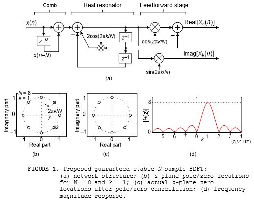
In Figure 1(b) we see the proposed network's real resonator has conjugate poles lying on the z‑plane's unit circle, for and N = 8 and k = 1, where the number 2 near the lower pole indicates dual zeros at $z = e^{-j2{\pi}k/N} = e^{-j{\pi}/4}$. The second of those dual zeros is produced by the feedforward stage of the network.
Due to pole/zero cancellation Figure 1(c) shows the network's equivalent z‑plane pole/zero locations. The proposed SDFT network's frequency magnitude response is given in Figure 1(d) for N = 8 and k = 1 where the peak response is located at $2{\pi}k/N = {\pi}/4$ radians/sample (corresponding to a cyclic frequency of $kf_s/N = f_s/8$ where fs is the x(n) input’s sample rate measured in Hz).
The Figure 1(a) network's time-domain impulse response is exactly k cycles of a complex exponential, whose frequency is $2{\pi}k/N$ radians/sample, having a duration of an N‑samples.
The Figure 1(a) network's transfer function is:$$H(z) = {e^{j2{\pi}k/N}-z^{-1}-e^{j2{\pi}k/N}z^{-N}+z^{-N-1}\over 1-2cos(2{\pi}k/N)z^{-1}+z^{-2}}.\qquad(1)$$The MATLAB/Octave code to display the frequency magnitude response of the Figure 1(a) network (for N = 8 and k = 1) is:
N = 8; k = 1;
B = [exp(j*2*pi*k/N), -1, zeros(1,N-2), -exp(j*2*pi*k/N), 1];
A = [1, -2*cos(2*pi*k/N), 1];
freqz(B, A, 512, 'whole')
Quantization of the center coefficient in the denominator in Eq. (1) will cause the real resonator's poles to shift, as will be discussed later, slightly from their desired positions along the unit circle. However, what is not widely known is that regardless of coefficient quantization the poles will always lie exactly on the z-plane’s unit circle guaranteeing resonator numerical stability [2]. So the proposed Figure 1 network produces the same spectral output samples as a single bin of an N‑point DFT with additional advantage that its output spectral samples are updated for each new input signal sample.
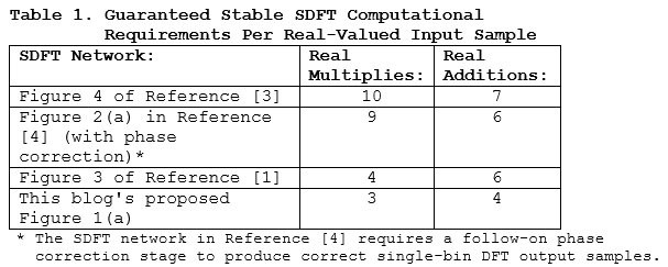
Proposed SDFT Computational Efficiency
The proposed Figure 1(a) guaranteed stable SDFT network is computationally more efficient than previously published guaranteed stable SDFT networks. That comparison is presented in Table 1.
The downloadable PDF file associated with this blog contains the following additional SDFT information:
• The effects of quantized coefficients on the Figure 1(a) SDFT,
• An SDFT signal tracking example,
• A brief tutorial on the traditional (unstable) SDFT,
• How to implement time-domain windowing with SDFTs,
• How to implement an SDFT for noninteger values of k.
Conclusions
I have proposed the most computationally efficient sliding DFT network, shown in Figure 1(a). That network computes a standard N‑point DFT's kth bin output on a real-time sample for sample basis and is guaranteed stable for all coefficient quantization scenarios.

References
[1] R. Lyons and C. Howard, “Improvements to the Sliding DFT Algorithm,” IEEE Signal Processing Mag., vol. 38, no. 4, pp. 119–127, July. 2021.
[2] R. Lyons, "Correcting an Important Goertzel Filter Misconception, dsprelated.com blog at: https://www.dsprelated.com/showarticle/796.php
[3] K. Duda, "Accurate, Guaranteed Stable, Sliding Discrete Fourier Transform,” IEEE Signal Processing Mag., vol. 27, no. 6, pp. 124–127, Nov. 2010.
[4] C. Orallo and I. Carugati, "Single Bin Sliding Discrete Fourier Transform", Chapter 2 of Fourier Transforms: High-tech Application and Current Trends, IntechOpen Limited, London, pp. 25-42, 2017.
- Comments
- Write a Comment Select to add a comment
Dear Rick,
thanks for your great blog article, it's very interesting! Especially the "doubling" trick.
In my conclusion, reducing the comb delay line length to N/2 in combination with doubling the frequency bins should result in the originally desired number of frequency bins.
This could be particularly advantageous in real-time audio applications, for example, where the shortest possible latency (impacted by the length of the comb delay line) is an important factor. But also frequency resolution as the counterpart to time resolution...
However, I'm not sure about the general "meaning" behind SDFT bin doubling.
Is it comparable to the classic FFT zero padding, where the increased number of resulting frequency bins is an effect of the interpolation and thus does not provide any higher frequency resolution than the original number of frequency bins?
Or would the doubling of the SDFT frequency bins lead to a higher frequency resolution, especially without the need for a larger comb delay line?
Juergen

Hello jurihock (Juergen).
Allow me to illustrate what I call "frequency doubling" with an example:
Let's consider a sliding DFT (SDFT) defined by N = 16 and the SDFT's input sequence is real-valued samples at a sample rate of 32 kHz. So we're only interested in the DFT resonant frequencies from zero Hz to Fs/2 Hz.
When the output of the comb filter's delay line is subtracted from the input sequence the available DFT bin-center frequencies are integer multiples of Fs/N (2000 Hz). Those frequencies are shown in the left column of the below table.
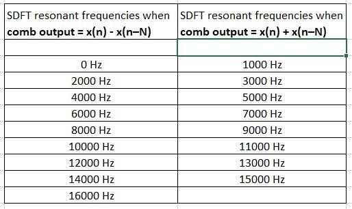
Now in an alternate implementation, when the output of the comb filter's
delay line is added to the input sequence the available DFT bin-center frequencies
are now the frequencies shown in
the right column of the above table.
So ..., for real-valued inputs, over the frequency range of zero to Fs/2 Hz we can set our SDFT bin center to be any of the frequencies in the left or right column of the above table. (No matter what SDFT bin-center frequency you choose, the SDFT's frequency magnitude response mainlobe's null-to-null width is 4000 Hz.)
Juergen, if you have any other questions for me please let me know.

Dear Rick,
Thank you very much for sharing,I implemented the sliding DFT algorithm from a blog using a fixed-point model, but I noticed significant fluctuations in the results of sqrt(real^2 + imag^2) when I used a relatively long input sequence. However, these fluctuations are much smaller with a floating-point model. Could you help me check if there is an issue with my fixed-point model implementation?
%%%%%%%%%%%%%%%%%%%%%%%%%%%%%%%%%%%%%%
my fixed_point code:
freqPoint = 128;
N = 1024;
Q = 15;
Qscale = 2^(Q);
L = 168960;
cosfreq = round(cos(2*pi*freqPoint/N)*Qscale );
sinfreq = round(sin(2*pi*freqPoint/N)*Qscale );
cosfreq2 = round(2*cos(2*pi*freqPoint/N)*Qscale);
in_delay = [zeros(N,1);in(:,1)];
temp1_delay1 = 0; temp1_delay2 = 0;
for i = 1:L
CombOut(i) = in(i) - in_delay(i);
CombOut(i) = CombOut(i) * Qscale;
temp2 = temp1_delay1 * cosfreq2;
temp1_delay2 = temp1_delay2 * Qscale;
temp1(i,1) = CombOut(i) + temp2 - temp1_delay2 ;
temp1(i,1) = round(temp1(i,1)/Qscale);
temp3 = temp1(i,1)*cosfreq;
temp1_delay1_cos = temp1_delay1 * Qscale;
CosValue(i) = temp3 - temp1_delay1_cos;
CosValue(i) = round(CosValue(i)/Qscale);
SinValue(i) = temp1(i,1)*sinfreq;
SinValue(i) = round(SinValue(i)/Qscale);
temp1_delay2 = temp1_delay1;
temp1_delay1 = temp1(i,1);
Amti_f(i,1) = round(sqrt(CosValue(i,1)^2 + SinValue(i,1)^2)*2/1024);
end
%%%%%%%%%%%%%%%%%%%%%%%%%%%%%%%%%%
This is data:(This is a segment of current sampling data with a sampling frequency of 6.4 kHz)
%%%%%%%%%%%%%%%%%%%%%%%%%%%%%%%%%%%
this is Amti jpg:


Hello wuwyw.
Your code looked like MATLAB code. But I was not able to run your code using MATLAB because I am not able to execute your 'in(:,1)' command.
I think your method of quantizing variables may be your problem.
wuwyw, try the following method for quantizing a variable:
Variable = round(Variable*Qscale)/Qscale;
Because your input signal's sample values are integers, and all of them are much less than 'Qscale', you do not need to quantize the 'CombOut(i)' variable.
Also, because the 'temp1' variable is quantized you do not need to quantize the 'temp1_delay1' and 'temp1_delay2' variables.
wuwyw, if my above suggestions do not work please let me know.
Did you notice that the "quantization" advice I gave you in my May 1, 2024, reply was not correct?
%%%%%%%%%%%%%%%%%%%%%%%
You are right, this is MATLAB code. Since the application scenario involves calculations with integer values, my code uses integers throughout. You mentioned the quantization method: Variable = round(Variable*Qscale)/Qscale, which results in fractional values. I tried this quantization method as well, but the issue with the amplitude growth still persists.Because the variable temp2 = temp1_delay1 * cosfreq2, where cosfreq2 has been quantized by multiplying with Qscale, I also multiplied CombOut(i) by Qscale to maintain consistent quantization in addition and subtraction operations.
%%%%%%%%%%%%%%%%%%%%%%%%
I have modified the code so it can be run directly. If it's convenient for you。%%%%%%%%%%%%%%%%%%%%%%%%
my fixed_point code:
clc;clear
load("D:\data.txt")
in = data;
L = 168960;%data Length
freqPoint = 128;%%frequency point
N = 1024;%%window length
Q = 15;%%coef bitwide
Qscale = 2^(Q);
%% coef quantizing
cosfreq = round(cos(2*pi*freqPoint/N)*Qscale );
sinfreq = round(sin(2*pi*freqPoint/N)*Qscale );
cosfreq2 = round(2*cos(2*pi*freqPoint/N)*Qscale);
%%
in_delay = [zeros(N,1);in(:,1)];
temp1_delay1 = 0; temp1_delay2 = 0;
for i = 1:L
CombOut(i) = in(i) - in_delay(i);
temp2 = temp1_delay1 * cosfreq2;
temp1(i,1) = CombOut(i)* Qscale + temp2 - temp1_delay2 * Qscale ;
temp1(i,1) = round(temp1(i,1)/Qscale);
temp3 = temp1(i,1)*cosfreq;
CosValue(i,1) = temp3 - temp1_delay1 * Qscale;
CosValue(i,1) = round(CosValue(i,1)/Qscale);
SinValue(i,1) = temp1(i,1)*sinfreq;
SinValue(i,1) = round(SinValue(i,1)/Qscale);
temp1_delay2 = temp1_delay1;
temp1_delay1 = temp1(i,1);
Amti_f(i,1) = round(sqrt(CosValue(i,1)^2 + SinValue(i,1)^2)*2/1024);
end
plot(Amti_f)
%%%%%%%%%%%%%%%%%%%%%%%%%%%%%%%%%%
This is data:(This is a segment of current sampling data with a sampling frequency of 6.4 kHz)
%%%%%%%%%%%%%%%%%%%%%%%%%%%%%%%%%%%
Your code does not quantize any variables. In you code you merely multiply all variables by 2^15 (a large number). For example, the variables 'cosfreq' and 'sinfreq' should be less than one. But your 'cosfreq' and 'sinfreq' variables are greater than 20,000!
I am trying to implement the quantization described in the "Answer" at:
https://dsp.stackexchange.com/questions/69223/how-...
Here is the code I am currently working on:
% Sliding DFT
% Richard Lyons [5/6/2024]
clear, clc
Input_Signal = readtable("Data.txt");
% Convert input data table to a 1 row 168960 column array
Input_Signal = reshape(table2array(Input_Signal), [1, 168960]);
Spec = fft(Input_Signal(1:1024));
Spec_Mag = abs(Spec);
Spec_Mag_dB = 20*log10(Spec_Mag/max(Spec_Mag));
figure(1), clf
subplot(2,1,1)
plot(Input_Signal, '-bs', 'markersize', 2)
axis([0, 2048, -3000, 3000]), title('Input')
%plot(Rick, '-bs', 'markersize', 4)
subplot(2,1,2)
plot(0:1023, Spec_Mag_dB, '-bs', 'markersize', 4)
title('1024-Pt DFT Spec Mag'), grid on, zoom on
%axis([0, 1024, 0, 0.4*10^7])
freqPoint = 128/4;
N = 1024/4;
Q = 15;
disp(' '), disp(['Q = ', num2str(Q)])
Qscale = 2^(Q); % 2^15 = 32768
L = 168960;
cosfreq = cos(2*pi*freqPoint/N);
cosfreq = Quantize(cosfreq, Qscale);
sinfreq = sin(2*pi*freqPoint/N);
sinfreq = Quantize(sinfreq, Qscale);
cosfreq2 = 2*cos(2*pi*freqPoint/N);
cosfreq2 = Quantize(cosfreq2, Qscale);
Temp1_Delay1(N+1) = 0; Temp1_Delay2(N+1) = 0;
CombOut = filter([1, zeros(1, 1024-1), -1], 1, Input_Signal);
%%%%%%%%%%%%%%%%%%%%%%%%%%%%%%%%%%%%
% Shift 'CombOut' sequence to the right by 1024 samples
%%%%%%%%%%%%%%%%%%%%%%%%%%%%%%%%%%%%
CombOut = [zeros(1, 1024), CombOut];
for K = N+1:L
temp2 = Temp1_Delay1(K)*cosfreq2;
temp2 = Quantize(temp2, Qscale);
temp1(K) = CombOut(K) + temp2 -Temp1_Delay2(K);
temp1(K) = Quantize(temp1(K), Qscale);
temp3 = temp1(K)*cosfreq;
temp3 = Quantize(temp3, Qscale);
CosValue = temp3 - Temp1_Delay1(K);
CosValue = Quantize(CosValue, Qscale);
SinValue = temp1(K)*sinfreq;
SinValue = Quantize(SinValue, Qscale);
Temp1_Delay2(K+1) = Temp1_Delay1(K);
Temp1_Delay1(K+1) = temp1(K);
AmtK_f(K) = sqrt(CosValue^2 + SinValue^2)*2/1024;
end
figure(2), clf
plot(AmtK_f, '-bs', 'markersize', 4), title('AmtK-f')
grid on, zoom on, xlabel('Time')
%%%%%%%%%%%%%%%%%%%%%%%%%%%%%%%%%%%%%%%%%%
% Compute TRUE Sliding DFT for comparison
%%%%%%%%%%%%%%%%%%%%%%%%%%%%%%%%%%%%%%%%%%%%
for Start = N+1:8*N
Spec = abs(fft(Input_Signal(Start-N+1:Start)));
Spec_TRUE(Start) = Spec(freqPoint+1)*2/N; % DFT Index 128
end
figure(3), clf
plot(Spec_TRUE, '-bs', 'markersize', 2), grid on, zoom on
title('True Sliding DFT Magnitude'), xlabel('Time')
%%%%%%%%%%%%%%%%%%%%%%%%%%%%%%%%%%%%%%%%%%
% Functions
%%%%%%%%%%%%%%%%%%%%%%%%%%%%%%%%%%%%%%%%%%
function [Y] = Quantize(X, Qscale)
%%%%%%%%%%%%%%%%%%%%%%%%%%
% Quantization used
%%%%%%%%%%%%%%%%%%%%%%%%%%
Factor = 2^8;
Y = X/Factor;
Y = round(Y*Qscale)/Qscale;
Y = Y*Factor;
% No quantization
% Y = X; %for M=1:10, disp('NO QUANTIZATION'), end
end
Hello wuwyw.
This sliding DFT network, being recursive, has infinite gain at its resonant frequency (frequency variable: 'freqpoint'). This makes the network difficult to implement using fixed point arithmetic, particularly when the DFT size (N) is large.
I was not able to implement the network in a reliable way using 16-bit data word widths (15 magnitude bits) when N = 1024.
But I was able to implement the network in a reliable way using 32-bit data word widths (31 magnitude bits) when N = 640.
For your particular "input" signal my new sliding DFT parameters and my new "quantization" function code are as follows:
L = 50000;
N = 640
freqPoint = N/8;
Q = 31;
%%%%%%%%%%%%%%%%%%%%%%%%%%%%%%%%%%%%%%%%%%
% Functions
%%%%%%%%%%%%%%%%%%%%%%%%%%%%%%%%%%%%%%%%%%
function [X_Quant] = Quantize(X, Qscale)
%%%%%%%%%%%%%%%%%%%%%%%%%%
% Quantization used
%%%%%%%%%%%%%%%%%%%%%%%%%%
Factor = 2^15;
X_Quant = X/Factor;
X_Quant = round(X_Quant*Qscale)/Qscale;
X_Quant = X_Quant*Factor;
% No quantization
% X_Quant = X; %for M=1:10, disp('NO QUANTIZATION'), end
In my previous posted (May 7 and May 9, 2024) code I was quantizing the variables 'cosfreq', 'sinfreq', and '2cosfreq' incorrectly. Here is my corrected code (NOTE: I also increased the 'Factor' variable.):
% Filename: Sliding_DFT_Lyons_for_dsprelated.m
% Sliding DFT for a person named "wuwyw" who (on 4/30/2024)
% commented on your sliding DFT blog at:
% https://www.dsprelated.com/showarticle/1533.php#co...
% Richard Lyons [5/14/2024]
clear, clc
Input_Signal = readtable("Data.txt");
% Convert input data table to a 1 row 168960 column array
Input_Signal = reshape(table2array(Input_Signal), [1, 168960]);
Spec = fft(Input_Signal(1:1024));
Spec_Mag = abs(Spec);
Spec_Mag_dB = 20*log10(Spec_Mag/max(Spec_Mag));
figure(1), clf
subplot(2,1,1)
plot(Input_Signal, '-bs', 'markersize', 2)
axis([0, 2048, -3000, 3000]), title('Input')
subplot(2,1,2)
plot(0:1023, Spec_Mag_dB, '-bs', 'markersize', 2)
title('1024-Pt DFT Spec Mag'), grid on, zoom on
N = 1024; % Must be an integer multiple of 128
freqPoint = N/8;
Q = 17 % Number of quantized data samples' magnitude bits
Qscale = 2^(Q);
%L = 168960;
L = 20000; % Number of input samples processed
cosfreq = cos(2*pi*freqPoint/N);
Factor = 2^0; % Begin to quantize 'cosfreq'
X_Quant = Factor*round((cosfreq/Factor)*Qscale)/Qscale;
sinfreq = sin(2*pi*freqPoint/N);
Factor = 2^0; % Begin to quantize 'sinfreq'
X_Quant = Factor*round((sinfreq/Factor)*Qscale)/Qscale;
cosfreq2 = 2*cos(2*pi*freqPoint/N);
Factor = 2^1; % Begin to quantize '2cosfreq'
X_Quant = Factor*round((cosfreq2/Factor)*Qscale)/Qscale;
Temp1_Delay1(N+1) = 0; Temp1_Delay2(N+1) = 0;
CombOut = filter([1, zeros(1, 1024-1), -1], 1, Input_Signal);
%%%%%%%%%%%%%%%%%%%%%%%%%%%%%%%%%%%%
% Shift 'CombOut' sequence to the right by 1024 samples
%%%%%%%%%%%%%%%%%%%%%%%%%%%%%%%%%%%%
CombOut = [zeros(1, 1024), CombOut];
for K = N+1:L
temp2(K) = Temp1_Delay1(K)*cosfreq2;
temp2(K) = Quantize(temp2(K), Qscale);
temp1(K) = CombOut(K) + temp2(K) -Temp1_Delay2(K);
temp1(K) = Quantize(temp1(K), Qscale);
temp3 = temp1(K)*cosfreq;
temp3 = Quantize(temp3, Qscale);
CosValue = temp3 - Temp1_Delay1(K);
CosValue = Quantize(CosValue, Qscale);
SinValue = temp1(K)*sinfreq;
SinValue = Quantize(SinValue, Qscale);
Temp1_Delay2(K+1) = Temp1_Delay1(K);
Temp1_Delay1(K+1) = temp1(K);
AmtK_f(K) = sqrt(CosValue^2 + SinValue^2)*2/1024;
end
figure(2), clf
plot(AmtK_f, '-bs', 'markersize', 2), title('AmtK-f')
grid on, zoom on, xlabel('Samples')
axis([0, length(AmtK_f), 0, max(AmtK_f)+10])
%%%%%%%%%%%%%%%%%%%%%%%%%%%%%%%%%%%%%%%%%%
% Compute TRUE Sliding DFT for comparison
%%%%%%%%%%%%%%%%%%%%%%%%%%%%%%%%%%%%%%%%%%%%
for Start = N+1:12*N
Spec = abs(fft(Input_Signal(Start-N+1:Start)));
Spec_TRUE(Start) = Spec(freqPoint+1)*2/N; % DFT Index N/8
end
figure(3), clf
plot(Spec_TRUE, '-bs', 'markersize', 2), grid on, zoom on
title('True Sliding DFT Magnitude'), xlabel('Samples')
axis([0, length(Spec_TRUE), 0, max(Spec_TRUE)+10])
%%%%%%%%%%%%%%%%%%%%%%%%%%%%%%%%%%%%%%%%%%
% Functions
%%%%%%%%%%%%%%%%%%%%%%%%%%%%%%%%%%%%%%%%%%
function [X_Quant] = Quantize(X, Qscale)
%%%%%%%%%%%%%%%%%%%%%%%%%%
% Quantization used
%%%%%%%%%%%%%%%%%%%%%%%%%%
Factor = 2^22;
X_Quant = Factor*round((X/Factor)*Qscale)/Qscale;
%%%%%%%%%%%%%%%%%%%%%%%%%%
% No quantization
%%%%%%%%%%%%%%%%%%%%%%%%%%
%X_Quant = X; %for M=1:10, disp('NO QUANTIZATION'), end
end

Rick,
I'd like to work out a more formal implementation of the original block diagram in fixed-point arithmetic, complete with scale factors of each of the data paths. Give me a few days to put this together.--Randy
Hi Rick,
This response is a follow-up to my comment on 15-May-2024 providing more details.
As far as I can tell, the Quantize() function, along with the variables Q and Qscale, do not do anything useful for the following reasons:
1) Since wuwxw's input data (from his data.txt file) is already integers, it is already quantized.
2) In the Quantize() function, the factor Qscale/Factor is used inside the round() function, and the inverse factor Factor/Qscale is used outside the round() function. Since these divisions are performed in floating point, it would be simpler (and in my opinion, easier to read) to utilize one variable b = Factor/Qscale and refactor the routine as follows:
function [X_Quant] = Quantize(X, b)
X_Quant = b * round((X/b);
end
3) The Quantize() function simply zeros (with rounding) the least significant log_2(b) bits to zero. This is not quantizing in the typical sense but rather re-quantizing.
4) The use of the letter "Q" is inappropriate in this context in my view. That is because within the context of fixed-point processing, Q is conventionally used to designate the scaling [1], and there is no scaling involved here.
5) The wordlength is not accounted for in this methodology. For example, there is no saturation or rollover as there would be when dealing with N-bit two's complement numbers.
--Randy
[1] Fixed-Point Numbers, MATLAB, https://www.mathworks.com/help/simulink/ug/fixed-p... (matlab-fixed-point-numbers)
Hi Randy.
I'm still studying the 'Quantize()' function in more detail. I'll get back to you.
Sure, no problem. I am also delayed in providing a detailed fixed-point implementation of this network. Please give me some more time.
I have however made some initial attempts to analyze the network and I'd like to share what I've found here and ask for corroboration or correction.
I initially reasoned this way: Since the comb filter has $N$ zeros on the unit circle at $z_k = \exp(j\cdot k \cdot 2\pi/N)$, $k = 0, 1, \ldots, N-1$, then its output will be zero when the input $x(n)$ is a sinusoid at any $k$, e.g., $\cos(n\cdot k\cdot 2\pi/N)$.
Thus at such a sinusoidal input frequency the input to the real resonator will be zero, and therefore the output of the resonator and everything after it will be zero!
This apparent contradiction arises because of an error in my analysis. I have attempted to find the output of the system using only steady-state behavior, but in case of this system the transient response behavior is crucial to the operation of the network.
What I found when I simulated this is that the output of the comb filter, while zero steady-state for a $k$-sinusoid, is NOT zero at startup. At startup the $z^{-N}$ delay line (assumed to be preloaded with zeros) has no effect for the first $N$ samples so the input signal is passed to the output of the comb filter. It is only after the $N$th sample that the comb filter output goes to zero.
Then I found that the first $N$ non-zero $k$-sinusoid samples out of the comb filter drive the resonator to a $k$-sinusoid $A_n\cos(n\cdot k\cdot 2\pi/N)$, where $A_n$ is a function of $n$, $n \le 0 \le N-1$. At $n = N$ the resonator reaches a peak amplitude $A_N\cos(N\cdot k\cdot 2\pi/N)$.
Then when the output of the comb filter drops to zero at the $n \ge N$, the resonator continues to resonate at $A_N\cos(n\cdot k\cdot 2\pi/N)$.
The final change comes when the input $x(n_f)$, $n_f \ge N$ drops to zero. Because of the stored $N$ samples stored in the delay line, the next $N$ output samples of the comb filter are again non-zero, and exactly equal to $-\cos(n\cdot k\cdot 2\pi/N)$.
These non-zero $N$ samples at the output of the comb filter drive the resonator sinusoid back to zero (ideally) and stop the oscillations.
Is this analysis correct? Does it match what you have observed?
This has been a wake-up call for me. All my life I've been lazy and relied on steady-state analyses. This shows that such analyses are not always reliable!
--Randy
Hi Randy.
What you described, in your June 11, 2024 Reply, matches what I see in my software modeling.

Hi Rick,
When I use your Octave code for freqz:
N = 8; k = 1;
B = [exp(j*2*pi*k/N), -1, zeros(1,N-2), -exp(j*2*pi*k/N), 1];
A = [1, -2*cos(2*pi*k/N), 1];
freqz(B, A, 512, 'whole')
I get the following plot, am I doing it wrong? as it is different from your plot.
Hi kaz.
Your plot is correct. Sorry for the confusion. I plotted
the spectrum in my blog's Figure 1(d) with a linear
vertical axis and zero Hz in the middle of the x-axis.
I did that in hopes of improving the plot's simplicity
and clarity.
However, in my MATLAB code I used the standard standalone
'freqz()" command which plots the spectrum with a logarithmic
vertical axis and zero Hz is at the very left end of the
x-axis. Again, sorry for the confusion.
kaz, try out the following MATLAB code:
%%%%%%%%%%%%%%%%%%%%%%%%%%%%%%%%N = 8; k = 1;
B = [exp(j*2*pi*k/N), -1, zeros(1,N-2), -exp(j*2*pi*k/N), 1];
A = [1, -2*cos(2*pi*k/N), 1];
[Spec, W] = freqz(B, A, 256, 'whole'); % Linear spectral vert. axis
Spec(k*256/N+1) = N; % Correct for the unwanted zero spec sample
Spec = fftshift(Spec); % Put zero Hz in the center of the x-axis
figure(1)
plot(linspace(-N/2, N/2, 256), abs(Spec))
ylabel('Linear'), xlabel('k'), grid on
%%%%%%%%%%%%%%%%%%%%%%%%%%%%%%%%%
Regarding the above oddball 'Spec(k*256/N+1) = N;' command, try
inserting a '%' at the beginning of that command
(%Spec(k*256/N+1) = N;) and run the code to see why I used that command.
at a frequency exactly equal to 'k' it ends up trying to compute zero
divided by zero, which is "mathematically undefined". In which case
MATLAB sets that "undefined" spectral sample value equal to zero
So my 'Spec(k*256/N+1) = N;' command eliminates that plotting problem.
I give a detailed explanation of this "mathematically undefined"
spectral sample topic in Section 3.13.1 of my "Understanding DSP" textbook.
Thanks Rick,
so you are saying that freqz arrives at 0/0 and sets it to 0 but isn't 0/0 = 0?
So do you see that the function is failing? if so why it doesn't replace it like you did?
I know log of zero is undefined. But this is something else.
Hi kaz. Your reply is interesting.
I don't know what the ratio of 0/0 means but I'm pretty that 0/0 does not equal zero. The ratio of 0/0 seems to be one of those simple mathematical expressions that no one knows what it means. So they call it "undefined', or "indeterminate".
I have not tried to examine the internal code in MATLAB's 'freqz()' function. But I'm willing to wager a pint of Kentucky bourbon that when the internal code encounters the calculation sin(0)/sin(0) = 0/0 the code assigns that ratio to be equal to zero.
In my SDFT analysis I know to set 0/0 equal to 'N' but MATLAB's 'freqz()' function wouldn't know what to do with 0/0.
Hi kaz.
If I win the pint of bourbon mentioned in my previous reply, I'll bring the pint over to your place and we can share it. However, if you live in Australia then you'll have to pay for my airfare to travel to your place.
Thanks Rick,
That is kind of you, you can use Amazon delivery service to UK to avoid the hassle of travel and queues.
Back to that pesky zero and apologies if I am off track:
Matlab functions (some) seem to detect zero division and manage it for example, it sets result to 1 here if x is zero:
%%%%%%%%%%%%%%%%%%%%%%%%%%%
M = 39; Fc = 20; Fs = 100;
x = linspace(-(M-1)/2,(M-1)/2,M);
h = sinc(x*2*Fc/Fs);
%%%%%%%%%%%%%%%%%%%%%%%%%%
but if I go my way, I need to detect and set the value:
x = linspace(-(M-1)/2,(M-1)/2,M);
x(x==0) = 10^-30; %avoid division by zero
h = sin(x*2*pi*Fc/Fs)./(x*2*pi*Fc/Fs);
%%%%%%%%%%%%%%%%%%%%%%%%%%%%%%%%%%%
Detecting division by zero has to be followed by a replacement but requires knowledge as what to replace with. The best way is to replace at source with some small value as I did above and let the calculation ran over it. That is if we can.
However with 0/0 and it might sound funny: We all agree N/0 => inf, to me this is not true always? I am more happy with 0/0 = 1
proof: 10^-30/10^-30 = 1 and we can approach 0/0 in the limit
Imagine what what else would I say if I drink that pint !
by the way if you set freqz to odd resolution the problem is over.
Hi kaz.
I like your 'sinc()' and sin(x)/x examples.
MATLAB's built-in 'sinc(x)' function checks to see if 'x' is ever equal to zero, in which case it sets the function's output sample equal to 1.
So you're happy with 0/0 = 1, huh? If I had to pick a value for 0/0 I'd follow the guidance of the famous British novelist Douglas Adams who claimed the most important number in the universe is 42. So I say:
0/0 = 42 (1)
I verify the above Eq. (1) by multiplying both sides by zero giving us:
0 = 0*42
which is correct. :-)
Dear Rick,
Thanks for sharing, this is great! However, if I use this for bin 0 (DC) and send a single sample impulse into it, the ouput won't ever reach 0 again. Since cos(0) = 1 the resonator part will continue forever? After N samples it will receive the negative impulse: x(N) - x(N-N) = -1. From there only zeros follow but the resonator part won't decay, it remains constant.
Anything wrong with this pseudo code?
comb = x[n] - x[n - N]
resonator = comb + (2 * cos(0) * z1) - z2
z2 = z1
z1 = resonator
Of course z1 and z2 are initialised to 0.
Thank you!
Kind regards,
Gustav
Hell gustl.
If you implement my blog's Figure 1 network properly, if N = 20 and k = 0 then its impulse response will be 20 unity-valued samples followed by a sequence of all zero-valued samples. That impulse response is equivalent to a simple 20-point moving averager.
If you have an application that requires 'k' to be k = 0, then it would smarter to use a moving average filter rather than my Figure 1 SDFT network.
gustl, I'm sorry but I don't understand your pseudo code, so I am not able to comment on it.
Hi Rick,
Yes, that‘s right, nothing wrong about your proposed network. However, if you just look at the resonator part when using k=0 I‘m a bit worried that it could overflow at some point. But on the other hand it doesn‘t really matter because for k=0 a moving average will work fine, as you said.
By the way, I‘ve got an implementation of a sliding DFT using lookup tables. It needs only 2 multiplies and 4 adds per bin but it needs to be phase corrected which requires another multiply and add. If you are interested I can send it to you.
Kind regards,
Gustav
Hello Gustav (gustl).
Regarding your Reply's first paragraph, you are correct. My Figure 1 network has poor pole/zero cancellation at z = 1 when k = 0. But as we agree, for k = 0 a simple moving average is the smarter implementation.
I'd be happy to look at your sliding DFT using a lookup table. You're welcome send information regarding your sliding DFT using a lookup table to me at:
R.Lyonws@ieee.org.
Thanks.
Hi Rick,
Thanks for the interesting article. I am having trouble understanding two implementation details with your network above.
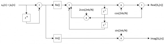
1. Would this network work for a complex-valued input signal? What would change if so? Would the real resonator portion only apply to the real part of the comb output, something like below?
2. In your reference [1] you discuss using non-integer values of k by adding a complex multiplication in the comb stage (Figure 5a). Would you be able to perform the same trick in this network? This also leads to the question above as the output of the comb will be complex-valued once this is implemented.
Thank you!
Adam Troyer
Hello Adam (amtroyer). I'm glad my blog is of some interest to you.
[Question# 1] You wrote, "Would this network work for a complex-valued input signal?" If your words "this network" mean my blog's Figure 1 network then the answer is yes. My blog's Figure 1 network does work with complex-valued inputs. The change from real-valued inputs to complex-valued inputs would be an increase in the required number of real-valued additions and multiplications per input sample.
I modeled your posted Reply's network and as far as I can tell it will not work properly with real-valued or complex-valued input signals.
[Question# 2] You wrote, "Would you be able to perform the same trick in this network?" Again, I don't know what your words "this network" mean? We're dealing with three networks here: (1) my blog's Figure 1 network, (2) your posted Reply's network, and (3) reference [1]'s Figure 5(a) network. So I don't know which of those networks your words "this network" is referring to.
Assuming your "this network" means my blog's Figure 1 network, the answer to your Question# 2 is, if you include a complex-multiply in my blog Figure 1 network's comb section then you can use a noninteger value for the 'k' variable.
Adam, if you have any further questions for me please let me know.
Hi Rick,
Sorry for the confusion with "this network". I should have chosen my words better! You were correct that I meant blog Figure 1 network in all of those instances.
Regarding question 1, I found the error I was making when using a complex-valued input and I have the blog Figure 1 network working correctly now for real and complex inputs.
Fixing this has brought me two more questions, if you don't mind my asking:
1. I am finding that with a complex-valued input the magnitude of the SDFT output is 2x larger than with a real-valued input. For example, if my input signal is a cos with amplitude of 1, then |X(k)|/(N/2) = 1 (after the initial N samples). If my input signal is a complex exponential with a magnitude of 1, |X(k)|/(N/2) = 2. Is this correct? If so, is this occurring because for a real-valued input half of the input signal power is in the -k bin, so it is not contributing to the output, while for a complex-valued input the entirety of the input signal power is in the k bin?
2. Why does the subtraction in the feedforward stage only get applied to the cos() leg and not the sin() leg?
Thanks for the help!
Adam
Hello Adam (amtroyer).
Regarding your first question: Your SDFT results are correct for a complex-valued input sequence. (That’s good news because it means your software modeling is correct. 😊) And your justification for your results is “essentially” correct. For a real-valued input sinusoid, containing exactly k cycles, half the spectral energy will be in the kth bin and the other half of the spectral energy will be in the (N-k)th bin.
As for your second question: I don’t have an answer, off the top of my head, on why there’s a subtraction in the feedforward stage’s real path and not in the imaginary path. The full details of how I derived my blog’s Figure 1 network are given in my blog’s Reference [1].
Hello Rick,
your article is really interesting (as every I had read to this moment - I am glad that you share your work in way that is understandable for most of us :) )
I have a question also connected to complex-valued SDFT solution based on Figure 1a network. (I have just read article and not yet checked this implementation and possibility to use it in algorithm which I ask below).
Is it able to use mentioned previously complex-valued SDFT in connection with algorithms that you proposed in article "Four ways to Compute an Inverse FFT Using the Forward FFT Algorithm" to implement SIDFT (Sliding Inverse Discrete Fourier Transform) or is there a better way to compute inverse transformation using proposed (mentioned in this article) SDFT algorithm?
Best regards,
Michal (Michael) Kaczmarek
Hello Michael. I just now saw your Reply here.
I've never thought about implementing a Sliding Inverse Discrete Fourier Transform (SIDFT) before now. But if I had to implement an SDFT the first thing I would try is the following:
Start with the following inverse DFT network.
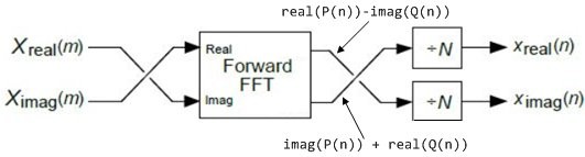
Replace the above "Forward FFT" block with the following forward Sliding DFT network:
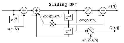
All of the processing in the forward SDFT network is complex-valued, so there are two comb filters, two 2nd-order resonators, six multipliers, etc.
Compute the real-valued "real(P(n))-imag(Q(n))" and "imag(P(n)) + real(Q(n))" sequences. Perform the final swapping shown in the inverse DFT network. And divide both real-valued swapped sequences by N.
Hello Rick,
Thank you very much for your response.
This was exactly my initial though on this topic. I will try this solution on my algorithm.
Best regards,
Michael
Hi Rick,
I think I see a problem at the top level of this architecture when implemented in fixed-point: it isn't necessarily stable. I could be wrong, let me explain and see if you agree or disagree.
The problem potentially occurs when the $cos(k\cdot\frac{2\pi}{N})$ and $sin(k\cdot\frac{2\pi}{N})$ constants in the feed-forward section are quantized. Depending on how these are quantized, isn't it possible that the magnitude of the pole at $e^{jk\cdot\frac{2\pi}{N}}$ is outside the unit circle, thus causing unbounded growth with a bounded input signal? I believe this is true in spite of the fact that the poles from the real resonator are guaranteed to be on the unit circle.
This is pointed out in your summary of the traditional SDFT in appendix A, specifically in figure A-3(b), but I don't see it mentioned in the main body of your alternate architecture.
--Randy
Hi Randy.
I claim that my Sliding DFT network is guaranteed stable. Stated in different words I say that with quantized coefficients the network's poles always remain exactly on the z-plane's unit circle. And with a "bounded" input sequence the network's complex-valued output will never grow without bound.
I also claim that quantizing the cos(2pik/N) and sin(2pik/N) feed-forward coefficients has no effect of network stability. Now, severe quantization of the cos(2pik/N) and sin(2pik/N) feed-forward coefficients does cause some very mild distortion of the network's |sin(x)/x| frequency magnitude response (in the vicinity of -kFs/N Hz, where Fs is the input sample rate) but does not cause any stability problems.
The network's critical coefficient is the 2cos(2pik/N) feedback coefficient. If that 2cos(2pik/N) feedback coefficient is infinitely precise the network's impulse response will be an N-sample (finite-duration) complex sinusoid whose frequency is kFs/N Hz. After those N samples all the remaining impulse response samples will be zero-valued. In that scenario we have perfect pole/zero cancellation on the z-plane.
Now if the 2cos(2pik/N) feedback coefficient is severely quantized the network's dual feedback poles shift along the unit circle away from our desired pole angles. Exact pole/zero cancellation no longer occurs on the z-plane. In this scenario the network's
impulse response will be an N-sample high-magnitude complex sinusoid
followed by an unwanted never-ending low-magnitude residual complex sinusoid. However, that unwanted residual complex sinusoidal output will never become unbounded.
Based on my above comments I recommend that the 2cos(2pik/N) feedback coefficient always be quantized with a minimum of 15 binary magnitude bits to obtain accurate sliding DFT results.
Rick,
Doh!!! It is a ZERO at $e^{jk\frac{2\pi}{N}}$, not a pole!
(Note to self: stop posting at 1am in the morning.)
To post reply to a comment, click on the 'reply' button attached to each comment. To post a new comment (not a reply to a comment) check out the 'Write a Comment' tab at the top of the comments.
Please login (on the right) if you already have an account on this platform.
Otherwise, please use this form to register (free) an join one of the largest online community for Electrical/Embedded/DSP/FPGA/ML engineers:


