Through the tube...
Hello all,
something completely different...
there was some recent discussion on the forum about modeling guitar amplifiers.
I have been wondering for quite a while, whether the methods that I use to model radio frequency power amplifiers might also work for audio applications.
It's been a rainy day, so I found the time and energy for some experiments. Just for fun.
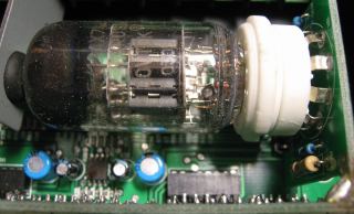
The device-under-test is a preamplifier with a single 12AX7 tube:

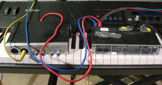
My good ol' Kurzweil (not in the picture) serves as "signal generator", and provides identical signals on two channels. The first channel goes into the preamp, then to the soundcard of my PC. The other channel is patched straight to the soundcard, and provides the "reference signal".
Picture: The "measurement setup"

I set the drive level to "moderate" distortion, and here we go:
This is the "dry" signal, straight from the keyboard. It is recorded without any effects, so it does sound a bit 'dry'.
Here (A) is the distorted output from the tube amp. Add some reverb and we're talking business...
To make a long story short, here (B) is the output from the model that I developed using Matlab.
The question is, does (B) sound like (A)? Please decide for yourself, for me it's "close enough".
Since it's all done in Matlab, it is easy to subtract the actual output signal (A) from the model output (B) to obtain the "error signal".
That's what I did. The file is here (better turn down the volume before listening...)
It is the output power from the actual amplifier that is unexplained by the model, boosted to 0 dB volume.
The absolute magnitude of the error signal is interesting: It is not obvious from the recordings, since they are all normalized:
The total error is more than 20 dB below the "nominal" output signal, leaving less than 1 % of the total output power from the amplifier unexplained.
I haven't done any further investigation into the physics of electron tubes (yet). The error spectrum might follow a 1/fn shape (flicker noise?)
Similarly, it is easy to calculate the tube distortion alone: Simply time-align and scale the signals from both amplifier input and output, then subtract them.
Here is the result, pure tube distortion. I'm using 4-times oversampling for the time alignment.
The model error sounds quite similar, but its amplitude is about 15 dB lower. In other words, less than 3 % of the power of the "intended" distortion product remain unexplained by the model.
Also, one can hear some "signal leakage" (high frequency "whistling"), because the input and output signals are simply subtracted without taking the frequency response into account.
Below the spectrum:
Green is the "clean" input signal.
Black is the output signal of the tube amplifier.
Red is the difference between tube amp output and model output.

The underlying model is Wiener-type, and as simple as it gets:a FIR filter and a polynomial.
Actually...
The FIR filter does improve the error magnitude by about 1.5 dB. But to be honest, I can't hear the difference.
Probably it could be omitted, leaving a simple polynomial as the model.
For comparison, I tried the same modeling with a transistor amplifier and less severe distortion.
There, the FIR filter models the highpass characteristics of the amp, and drops the error magnitude below -50 dB.
If anybody is interested, I could write more about how to derive the model from "measured data".
Essentially, it is a single least-squares fit over a couple of 100000 points that finds both the polynomial coefficients and the FIR filter taps simultaneously.
So much for now!
Cheers
Markus
- Comments
- Write a Comment Select to add a comment
To post reply to a comment, click on the 'reply' button attached to each comment. To post a new comment (not a reply to a comment) check out the 'Write a Comment' tab at the top of the comments.
Please login (on the right) if you already have an account on this platform.
Otherwise, please use this form to register (free) an join one of the largest online community for Electrical/Embedded/DSP/FPGA/ML engineers:


