


Allpass Digital Waveguide Networks
We now describe the class of multi-input, multi-output (MIMO) allpass filters which can be made using closed waveguide networks. We will see that feedback delay networks can be obtained as a special case.
Signal Scattering
The digital waveguide was introduced in §2.4. A basic fact from acoustics is that traveling waves only happen in a uniform medium. For a medium to be uniform, its wave impedance3.17must be constant. When a traveling wave encounters a change in the wave impedance, it will reflect, at least partially. If the reflection is not total, it will also partially transmit into the new impedance. This is called scattering of the traveling wave.
Let ![]() denote the constant impedance in some waveguide, such as a
stretched steel string or acoustic bore. Then signal scattering is
caused by a change in wave impedance from
denote the constant impedance in some waveguide, such as a
stretched steel string or acoustic bore. Then signal scattering is
caused by a change in wave impedance from ![]() to
to ![]() . We can
depict the partial reflection and transmission as shown in
Fig.2.33.
. We can
depict the partial reflection and transmission as shown in
Fig.2.33.
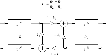
The computation of reflection and transmission in both directions, as shown in Fig.2.33 is called a scattering junction.
As derived in Appendix C, for force or pressure waves, the
reflection coefficient ![]() is given by
is given by
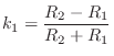
That is, the coefficient of reflection for a traveling pressure wave leaving impedance
For velocity traveling waves, the reflection coefficient is
just the negative of that for force/pressure waves, or ![]() (see
Appendix C).
(see
Appendix C).
Signal scattering is lossless, i.e., wave energy is neither
created nor destroyed. An implication of this is that the
transmission coefficient
for a traveling pressure wave leaving impedance ![]() and entering
impedance
and entering
impedance ![]() is given by
is given by
Digital Waveguide Networks
A Digital Waveguide Network (DWN) consists of any number of digital waveguides interconnected by scattering junctions. For example, when two digital waveguides are connected together at their endpoints, we obtain a two-port scattering junction as shown in Fig.2.33. When three or more waveguides are connected at a point, we obtain a multiport scattering junction, as discussed in §C.8. In other words, a digital waveguide network is formed whenever digital waveguides having arbitrary wave impedances are interconnected. Since DWNs are lossless, they provide a systematic means of building a very large class of MIMO allpass filters.
Consider the following question:
Under what conditions may I feed a signal from one point inside a given allpass filter to some other point (adding them) without altering signal energy at any frequency?In other words, how do we add feedback paths anywhere and everywhere, thereby maximizing the richness of the recursive feedback structure, while maintaining an overall allpass structure?
The digital waveguide approach to allpass design [430] answers this question by maintaining a physical interpretation for all delay elements in the system. Allpass filters are made out of lossless digital waveguides arranged in closed, energy conserving networks. See Appendix C for further discussion.
Next Section:
The Reverberation Problem
Previous Section:
Allpass Filters


