


Choice of Delay Lengths
Following Schroeder's original insight, the delay line lengths in an
FDN (![]() in Fig.3.10) are typically chosen to be mutually
prime. That is, their prime factorizations contain no common
factors. This rule maximizes the number of samples that the lossless
reverberator prototype must be run before the impulse response
repeats.
in Fig.3.10) are typically chosen to be mutually
prime. That is, their prime factorizations contain no common
factors. This rule maximizes the number of samples that the lossless
reverberator prototype must be run before the impulse response
repeats.
The delay lengths ![]() should be chosen to ensure a
sufficiently high mode density in all frequency bands. An
insufficient mode density can be heard as ``ringing tones'' or an
uneven amplitude modulation in the late reverberation impulse
response.
should be chosen to ensure a
sufficiently high mode density in all frequency bands. An
insufficient mode density can be heard as ``ringing tones'' or an
uneven amplitude modulation in the late reverberation impulse
response.
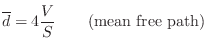
Mean Free Path
A rough guide to the average delay-line length is the ``mean free path'' in the desired reverberant environment. The mean free path is defined as the average distance a ray of sound travels before it encounters an obstacle and reflects. An approximate value for the mean free path, due to Sabine, an early pioneer of statistical room acoustics, is
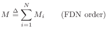
Mode Density Requirement
A guide for the sum of the delay-line lengths is the desired
mode density. The sum of delay-line lengths ![]() in a lossless
FDN is simply the order of the system
in a lossless
FDN is simply the order of the system ![]() :
:
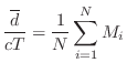
Since the order of a system equals the number of poles, we have that
![]() is the number of poles on the unit circle in the lossless
prototype. If the modes were uniformly distributed, the mode density
would be
is the number of poles on the unit circle in the lossless
prototype. If the modes were uniformly distributed, the mode density
would be ![]() modes per Hz. Schroeder [417]
suggests that, for a reverberation time of 1 second, a mode density of
0.15 modes per Hz is adequate. Since the mode widths are inversely
proportional to reverberation time, the mode density for a
reverberation time of 2 seconds should be 0.3 modes per Hz, etc. In
summary, for a sufficient mode density in the frequency domain,
Schroeder's formula is
modes per Hz. Schroeder [417]
suggests that, for a reverberation time of 1 second, a mode density of
0.15 modes per Hz is adequate. Since the mode widths are inversely
proportional to reverberation time, the mode density for a
reverberation time of 2 seconds should be 0.3 modes per Hz, etc. In
summary, for a sufficient mode density in the frequency domain,
Schroeder's formula is
Prime Power Delay-Line Lengths
When the delay-line lengths need to be varied in real time, or
interactively in a GUI, it is convenient to choose each delay-line
length ![]() as an integer power of a distinct prime number
as an integer power of a distinct prime number ![]() [457]:
[457]:
Suppose we are initially given desired delay-line lengths ![]() arranged in ascending order so that
arranged in ascending order so that
![$\displaystyle \left[\frac{\log(M_i)}{\log(p_i)}\right]
\isdefs \left\lfloor 0.5 + \frac{\log(M_i)}{\log(p_i)}\right\rfloor.
$](http://www.dsprelated.com/josimages_new/pasp/img808.png)
This prime-power length scheme is used to keep 16 delay lines both variable and mutually prime in Faust's reverb_designer.dsp programming example (via the function prime_power_delays in effect.lib).
Next Section:
Achieving Desired Reverberation Times
Previous Section:
Choice of Lossless Feedback Matrix


