


A Direct Digital Synthesizer with Arbitrary Modulus
Suppose you have a system with a 10 MHz sample clock, and you want to generate a sampled sinewave at any frequency below 5 MHz on 500 kHz spacing; i.e., 0.5, 1.0, 1.5, … MHz. In other words, f = k*fs/20, where k is an integer and fs is sample frequency. This article shows how to do this using a simple Direct Digital Synthesizer (DDS) with a look-up table that is at most 20 entries long. We’ll also demonstrate a Quadrature-output DDS. A note on terminology: some authors call a DDS a Numerically-Controlled Oscillator (NCO).
Disclaimer: I have not implemented this DDS in hardware, so there could be problems with the scheme that I have not anticipated.
This article is available in PDF format for easy printing.
Background [1,2]
A continuous-time sinewave with frequency f0 is given by y = sin(2πf0t + φ0). For a sampled signal, we replace t by nTs, where n is the sample number and Ts is the sample time. Letting φ0 = 0, we have:
y = sin(2πf0nTs)
The phase of the signal is:
Φ = 2πf0nTs rad (mod 2π),
Or
Φ = f0nTs cycles (mod 1) (1)
The phase wraps every 2π radians = 1 cycle. Equation 1 shows that the phase increases (accumulates) by f0Ts every sample. So we can calculate the phase using an accumulator with input = f0Ts, as shown in Figure 1a. The value of φ has a range of 0 to 1 (cycles). We generate the sinewave from the phase using a look-up table (LUT). What we’ve just described is a basic DDS. Note that another option to generate the sinewave from the phase not discussed here is the CORDiC algorithm [3].
Figure 1b adds quantization in the accumulator register, the phase, and the LUT entries. The accumulator input has 2C steps over a range of 0 to 1, giving a frequency step Δf = fs/2C, where fs is the sample frequency. The resulting output frequencies are fs/2C, 2fs/2C, 3fs/2C … Given the 2C steps, we can say the DDS has a modulus of 2C. As an example, if C= 24 bits, and fs= 10 MHz, the frequency step is:
Δf = 10E6/224 = 0.59605 Hz.
This frequency step is impressively small. However, if you want to program a frequency that is not on one of the steps, such as fs/10, there will be a small frequency error of up to Δf/2.
If we were to maintain the 24 bits of phase, the LUT size for this example, taking symmetry of the sine into account, would be ¼*224 = 222 = 4,194,304 entries. To avoid such a large LUT, the phase is normally quantized to P < C bits. The phase quantization results in so-called phase truncation spurs in the output spectrum. A typical value of P used in DDS chips is 15 bits, which, taking advantage of the symmetry of the sine, gives LUT size of 213= 8192 entries.
You can see that a standard DDS is not a perfect solution to our problem of generating f0 = k*fs/20: it does not produce the exact frequency; it requires a not-so-small LUT; and it has spurs due to truncation of the phase.(Note that there are techniques for reducing phase-truncation spurs [4]).
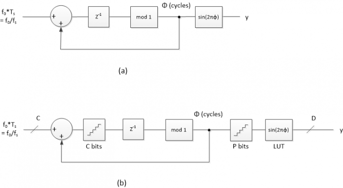
Figure 1. a) Implementation of Equation 1. b) DDS with quantization.
DDS with Arbitrary Modulus
A DDS with modulus other than 2C can address the shortcomings of a conventional DDS for our application.
If we multiply both sides of Equation 1 by an integer L, we get:
LΦ = Lf0nTs (mod L)
This equation can be implemented by modifying the accumulator in Figure 1a as shown in Figure 2. Here we require m to be an integer between 0 and L-1, so there are L entries in the LUT, where L is not restricted to 2C. The input L*f0/fs is an integer:
L*f0/fs = k (2)
or f0 = k*fs/L (3)
Since k is an integer, f0 has a step size of Δf = fs/L. For a given Δf and fs, we have:
L = fs/Δf (4)
Letting fs = 10 MHz and Δf= 0.5 MHz, we get L= 20. The number of bits required for the accumulator is found by taking log2(L) and rounding up to the next integer. For L= 20, we need 5 bits.
As shown in Figure 2, m = Lφ, so the phase is φ = m/L. Simplistically, the LUT entries are:
u(m) = sin(2πm/L), m= 0: L-1 (5)
However, for fixed point entries, we need to round the values of u(m) and prevent overflow when m = L/4 and u(L/4) = sin(π/2) = 1.0. (For example, if the number of bits D= 8, the largest allowable entry is not 1.0 but (27 -1)/27 = 127/128 = 01111111). We can compute the fixed-point entries as:
u(m) = (1 – ε) * sin(2πm/L), m= 0: L-1
LUT(m) = round(u(m)*2D-1)/2D-1 (6),
Where D is the number of bits in the 2’s complement LUT entry and ε << 1. I used ε= 1/2D-2. Multiplication by 1 – ε makes the LUT entry for m = L/4 less than 1.0 after rounding.
For our case, with L= 20, the LUT values are plotted in figure 3. The LUT contains one cycle of a sinewave evaluated over L samples. Note that when L is a multiple of 4, it is possible to reduce the LUT size to L/4 entries by taking the symmetry of the sinewave into account.
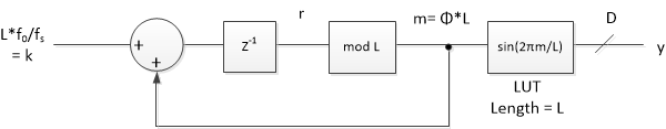
Figure 2. DDS with arbitrary modulus
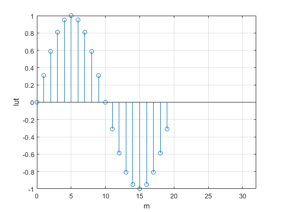
Figure 3. Sine look-up table for L= 20
Let’s look at the behavior of our example DDS, with fs = 10 Hz and Δf = 0.5 Hz. The Matlab code is listed in the Appendix. To start out, let the output frequency f0= 0.5 Hz. From equations 2 and 4, k = f0/Δf, so k= 1. As shown in Figure 4, m increments through all the integers from 0 to L-1, then repeats. So the DDS just steps through every entry of the LUT. Also shown in Figure 4 is the phase φ = m/L cycles, and the sampled sinewave output.
Now, if we let f0 = 1 Hz, k = 2. Thus m = 0, 2, 4, … and the DDS steps through every 2nd entry of the LUT, as shown in Figures 5a and 5b.
If we let f0 = 1. 5 Hz, k= 3. Thus m= 0, 3, 6, … and the DDS steps through every 3rd entry of the LUT, as shown in Figures 5c and 5d. As can be seen in Figure 5c, it takes three cycles for the phase sequence to repeat.
For L= 20, the allowable output frequencies f0 that are less than fs/2 are: 0.5, 1, 1.5, 2, 2.5, 3, 3.5, 4, and 4.5 Hz, corresponding to k = 1: 9. For L even, there are L/2 -1 allowable values of f0.
Since accumulator output m is always an integer, there is no phase truncation error. The only error in the output y is due to rounding of the LUT entries. Figure 6 compares spectra for f0 = 1.5 Hz of a conventional DDS with 15-bits of phase to our DDS with L= 20 (4.3 bits of phase). Both have 16-bit LUT entries. The modulus 20 DDS has lower spurious, with the worst spur at about -105 dB with respect to the level at 1.5 Hz.
Finally, note that it is also possible to make a DDS with an arbitrary programmable modulus.The approach involves using two accumulators [5,6].
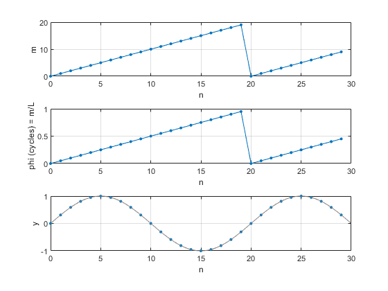
Figure 4. DDS with L= 20 and fs = 10 Hz.
a) Accumulator output m for f0 = 0.5 Hz. b) Phase in cycles. c) LUT output y.
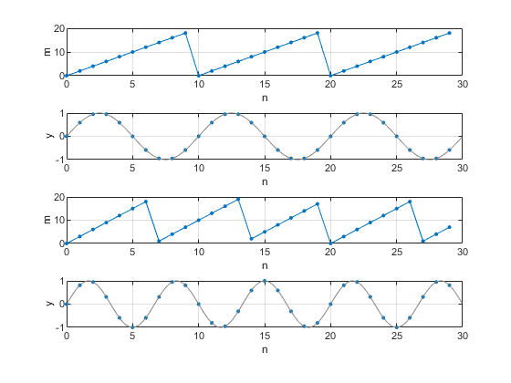
Figure 5. DDS with L= 20 and fs = 10 Hz.
a) Accumulator output m for f0 = 1.0 Hz, and
b) LUT output y
c) Accumulator output m for f0 = 1.5 Hz, and
d) LUT output y
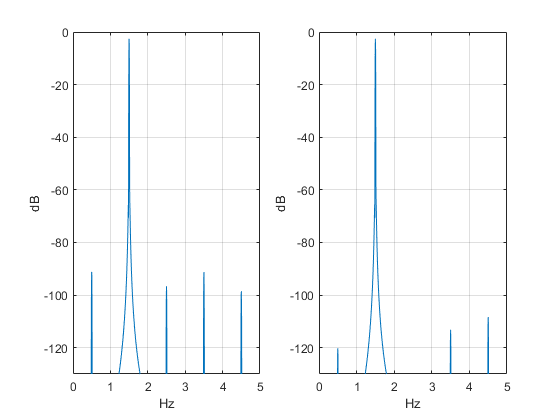
Figure 6. Spectra of conventional DDS and DDS with modulus 20. f0 = 1.5 Hz and fs = 10 Hz.
Left: Conventional DDS with 15 bits of phase and 16-bit LUT entries.
Right: DDS with L= 20 (4.3 bits of phase) and 16-bit LUT entries.
Quadrature Output DDS
A quadrature output DDS has both cosine and -sine outputs. The cosine phase leads sine phase by π/2 radians = ¼ cycle. Given m as the LUT address for a sine, the address for the cosine is:
p = m + L/4 mod(L)
where L is the DDS modulus = LUT length, which must be a multiple of 4. We can modify the Matlab code in the Appendix to compute both sine and cosine. Here is the modified for loop:
    sine(1)= 0;
    cosine(1)= 1;
    m= 0;
    for n= 2:N
        r = k + m;
        m= mod(r,L);            % LUT address/ sine
        p= mod(m+ L/4,L);       % LUT address/ cosine
        sine(n)= lut(m+1);      % sine output
        cosine(n)= lut(p+1);    % cosine output
    end
The Quadrature DDS outputs for L= 20, fs= 10 Hz, and f0 = 1 Hz are shown in Figure 7.
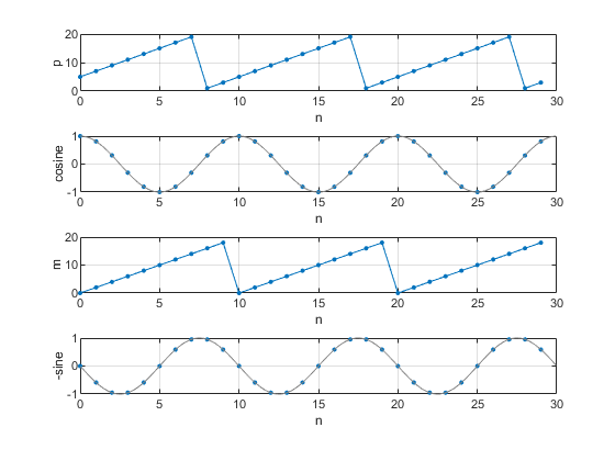
Figure 7. Quadrature DDS with L= 20, fs = 10 Hz, and f0 = 1 Hz.
a. cosine address p. b) cosine output. c) sine address m. d) -sine output.
Simplest DDS with L= 4
If we let L= 4, there is only one output frequency below fs/2:
f0 = k*fs/L = fs/4 (k= 1)
The LUT sine values from Equation 5 are:
LUT = [0 sin(π/2) 0 sin(3π/2)]
= [0 1 0 -1]
The cosine values are [1 0 -1 0].
A quadrature L= 4 DDS using cosine and -sine can be used to down-convert a signal centered at fs/4 to complex baseband [7,8]. Since all LUT values are 0 or +/-1, no multiplier is needed to perform the frequency conversion.
References
- MT-085, “Fundamentals of Direct Digital Synthesis (DDS)”, Analog Devices, 2009, https://www.analog.com/media/en/training-seminars/tutorials/MT-085.pdf
- “A Technical Tutorial on Digital Signal Synthesis”, Analog Devices, 1999, https://www.analog.com/media/cn/training-seminars/tutorials/450968421DDS_Tutorial_rev12-2-99.pdf
- Rice, Michael, Digital Communications, A Discrete-Time Approach, Pearson, 2009, section 9.4.
- Rice, section 9.2.
- Gentile, Ken, AN-953, “Direct Digital Synthesis with a Programmable Modulus”, Analog Devices, 2014, https://www.analog.com/media/en/technical-documentation/application-notes/AN-953.pdf
- Hou, Yuqing, et. al., “An Accurate DDS Method Using Compound Frequency Tuning Word and Its FPGA Implementation”, Electronics, Nov, 2018, https://www.mdpi.com/2079-9292/7/11/330
- Harris, Fredric J., Multirate Signal Processing, Prentice-Hall PTR, 2004, section 13.2.1.
- Lyons, Richard G., Understanding Digital Signal Processing, 3rd Ed., Prentice-Hall, 2011, section 13.1.2.
Neil Robertson June 3, 2019. Revised 6/8/19
Appendix Matlab Code for DDS with Modulus = 20
% dds_mod20.m  5/30/19   Neil Robertson
% DDS with modulus L = 20
% output frequency f0 = k*fs/L
% Plot LUT, phase, and output
fs= 10;                     % Hz sample freq
df= 0.5;                    % Hz desired freq step
L= fs/df                    % length of LUT= modulus of accumulator
if mod(L,1)~=0
    error('fs/fstep must be an integer')
end
% create LUT with one full cycle of sinewave (not using symmetry)
D= 16;                       % bits LUT entries quantization
m= 0:L-1;
phi_lut= m/L;                % cycles phase
epsilon= 1/2^(D-2);
u= (1 - epsilon) *sin(2*pi*phi_lut);
lut= round(u*2^(D-1))/(2^(D-1));      % quantize lut entries
%
% DDS
N= 30;                             % number of output samples
f0= 0.5;                           % Hz output frequency (must be multiple of df)
k= L*f0/fs;                        % integer input to DDS
y(1)= 0;
m= 0;
for n= 2:N
    r = k + m;
    m= mod(r,L);                   % LUT address
    y(n)= lut(m+1);                % output
        phi(n)= m/L;               % cycles phase
end
%
%
% Plotting
%
% plot LUT
stem(0:L-1,lut),grid
axis([0 32 -1 1])
xlabel('m'),ylabel('lut'),figure
%
%plot m and phi
subplot(311),plot(0:N-1,phi*L,'.-','markersize',9),grid
axis([0 N 0 20])
xlabel('n'),ylabel('m')
subplot(312),plot(0:N-1,phi,'.-','markersize',9),grid
axis([0 N 0 1])
xlabel('n'),ylabel('phi (cycles) = m/L')
%
% plot y along with "continuous" sinewave y2 in grey
fs_plot= fs*16;                  % fs of "continuous" sine
Ts= 1/fs_plot;
Len= 16*N;
i= 0:Len-1;
y2= sin(2*pi*f0*i*Ts);           % "continuous" sine
subplot(313),plot(0:N-1,y,'.','markersize',9),grid
hold on
plot(i/16,y2,'color',[.5 .5 .5])
axis([0 N -1 1])
xlabel('n'),ylabel('y')
- Comments
- Write a Comment Select to add a comment

Hi Neil,
Thanks for the useful subject. I have only few things to add.
1) DDS term was coined for the physical NCO chip plus ADC (actually DAC, as Neil pointed below) and marketed as such. The NCO is more generic term to indicate actual cos/sin function generator at digital level.
2) a dedicated NCO that targets specific frequencies to centre on the target bins is a preferred requirement in some applications over generic NCO (based on modulo 2) for two reasons;a nondedicated NCO can suffer bin shift and phase drift though frequency tends to be accurate over long time window. The phase drift occurs because of rounding of tuning word calculation right at start. The accumulator itself is not truncated and wraps around if modulo 2.
3) The use of LUT here is just another case of using precomputation approach which can be applied to any equation (fully or partially precomputed). The address then represents input to precomputation table.
If lookup table can't cover enough resolution then intermediary values can be derived on the fly by interpolation leading to larger virtual LUT.
The cordic is direct computation of each value of cos/sin at given point of phase.
4) I am not familiar with your matlab code for cos/sin lut generation. I just write this for a full cycle table:
lut = round(2^15*exp(j*2*pi*(0:N-1)/N));
Then I model NCO emulating the accumulator plus addressing.
Some engineers prefer their LUT calculation to target centre of step rather than edges.
5) A generic NCO with small LUT compared to accumulator bitwidth and no intermediate computations may be ok for some applications if phase accuracy is more of interest such as PLLs.
NCO ip vendors specify three elements of resolution:
LUT resolution (size)
phase resolution (accumulator width)
amplitude resolution (bit width)
Regards
Kaz

Thanks Kaz,
Did you mean to say DAC rather than ADC in item 1?
yes DAC indeed
This is a great way to produce frequencies - provided you are creating the DDS yourself, in an FPGA core. The alternative? Use standard parts, and customise the clock.
Example: Consider the 10 MHz clock you started out with. A standard DDS chip is the AD9851, which can be clocked at up to 180 MHz. It has a 32-bit counter, so if you use a frequency step of 1/24 Hz, the clock needs to be:
(2^32) / 24 = 178,956,970.6667 Hz
Remember that 10 MHz clock from the original specs? Let me introduce: the si5351. Using the 10 MHz signal, you program a multiplier to ensure the internal VCO runs between 600 and 900 MHz. An interger of 71, a numerator of 136,591 and a denominator of 234,374 will get you (roughly): 715,827,882.66667 Hz.
An internal divide by 4 gives: 178,956,970.6667 Hz with an error of about 1x10^ -15.
Accurate frequencies, within +/- 1/24 Hz, all the way up to about 60 MHz.
So yeah, I'll keep your method in mind, if I ever get to implement a DDS in an FPGA. Meanwhile, if you ever need to use standard parts, consider adding the si5351 to your clock source.
Hi Alan,
Thanks for the tip. It is useful to get a hardware perspective on the problem.
regards,
Neil
To post reply to a comment, click on the 'reply' button attached to each comment. To post a new comment (not a reply to a comment) check out the 'Write a Comment' tab at the top of the comments.
Please login (on the right) if you already have an account on this platform.
Otherwise, please use this form to register (free) an join one of the largest online community for Electrical/Embedded/DSP/FPGA/ML engineers:


