


Bank-switched Farrow resampler
Bank-switched Farrow resampler
Summary
A modification of the Farrow structure with reduced computational complexity.
Compared to a conventional design, the impulse response is broken into a higher number of segments. Interpolation accuracy is achieved with a lower polynomial order, requiring fewer multiplications per output sample at the expense of a higher overall number of coefficients.
Example code
This code snippet provides a Matlab / Octave implementation.
And here is the same in C, with explicit sample-per-sample calculation that allows varying the output rate even during operation (the Matlab version is vectorized).
Background
A Farrow structure resamples a signal at an arbitrary, possibly time-varying sampling rate. It utilizes a piecewise polynomial approximation of a continuous-time impulse response.
The proposed variant uses multiple segments per tap instead of one. This may allow to achieve the same accuracy with a lower order polynomial.
Note:
The performance of a Farrow resampler depends mainly on
- The ideal impulse response itself (filter prototype, cutoff frequency, steepness, far-off rejection, limitations from finite duration / limited number of taps)
- The accuracy of the polynomial approximation to the ideal impulse response
The proposed bank switching can improve the approximation accuracy, but the approximation can obviously not outperform the ideal impulse response. In other words, any attempt to improve performance by better approximation accuracy of the impulse response is futile, when the ideal impulse response itself is the limiting factor.
Concept
"Bank-switching" breaks the interpolation segments into smaller pieces.
Fig. 1 shows an example for an impulse response implemented in a conventional Farrow resampler.
Each segment corresponds to one sample of the input signal at a time. The resampler interpolates the impulse response at the sample duration, multiplies with the sample sample and sums the resulting product over all taps at the output.
To calculate the next output sample, the input stream is shifted, for example by 1/3 sample for an output rate that is 3x higher than the input rate. Either a sample stays within its impulse response segment, or it moves to the next tap (segment) by shifting the delay line.
Since the shape of an impulse response can be rather complex over the duration of one segment, a high-order polynomial is required to approximate it with the required accuracy. The arrows in Fig. 1 point out an example segment.
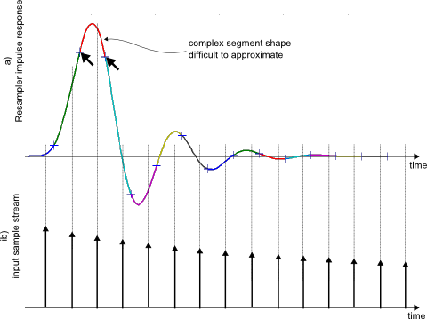
Fig.1: Resampler impulse response segments (a) and input signal (b)
The proposed structure breaks each segment of the impulse response into n sub-segments. This is shown in Fig. 2, with n=2. Since segments become shorter, an accurate approximation can be achieved with a lower-order polynomial.
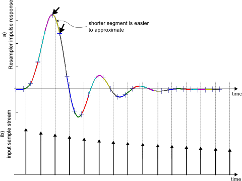
Fig.2: Resampler impulse response broken into sub-segments (a) and input signal (b)
Only every second impulse response segment contributes to the output signal at any given time. Therefore, the number of taps remains unchanged. The interpolator can use bank-switching between alternative polynomial coefficient sets in each tap.
Similarity with polyphase FIR upsampler
The bank-switching concept can be understood in terms of a conventional polyphase FIR interpolator, which is recalled below:
 :
:
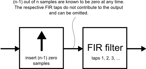
Fig.3: Interpolation using FIR filter
As shown in Fig. 3, interpolation by an integer factor n can be performed by inserting (n-1) zero samples and subsequent FIR filtering.
Zero samples do not contribute to the output of the FIR filter and their location in time is always known. Therefore, the structure can be rearranged into the polyphase arrangement in Fig. 4. The term "polyphase" highlights that each coefficient bank generates a different "phase" of the signal, that is, a replica that is delayed by a varying amount.
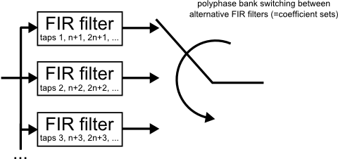
Fig.4: Polyphase FIR interpolator
Instead of fixed FIR coefficients in Fig. 4, the bank-switched Farrow interpolator uses polynomial interpolation (Fig. 5).
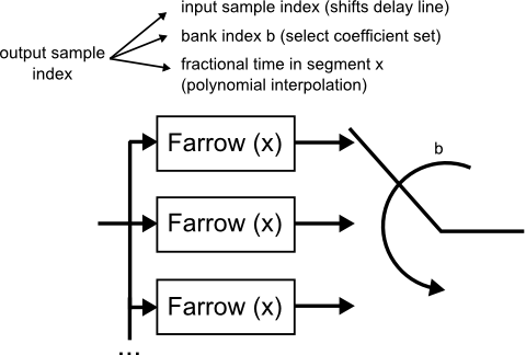
Fig.5: Bank-switched Farrow structure
The time instant of each output sample is split into:
- A first integer part that corresponds to the position in the input stream. A change results in shifting the delay line and processing one (or more) new input samples.
- A second integer part that determines the coefficient bank
- A fractional part that interpolates each bank's impulse response segment.
The calculation is explicitly written out in the C implementation.
Efficient use
A Farrow interpolator that requires 3rd or higher approximation order may be a good candidate for bank switching. Reducing 2nd order to linear is usually not practical, since the number of sub-segments needed to maintain accuracy grows too large. These numbers should be taken with caution, since accuracy requirements may differ by several orders of magnitudes, depending on the application.
In any case, some trial-and-error with alternative designs may be useful to find the best solution. Your mileage may vary.
- Comments
- Write a Comment Select to add a comment

what can be the possible choice of the bank index? can it be the interpolation factor?

Hi,
edit: thinking about your question again: It's equivalent to interpolation by an integer factor (zero sample insertion) before the structure, if that's what you meant.
Now if the interpolation factor implemented by the structure (!) is an integer, the problem reduces to a plain polyphase filter with fixed coefficients (e.g. a FIR structure with as many "banks" of coefficients as there are "phases" of each input sample = interpolation factor). In that sense I'm not sure I understand the intent behind the question.
But let me take back a step from this 10-year old article. To recap,
- Arbitrary resampling is implemented by a FIR structure with coefficients that aren't constant but computed as a function of the output sample's fractional phase
- A "conventional" Farrow structure computes each FIR coefficient using a polynomial of said fractional phase
- My proposal from the article is to break that polynomial into multiple segments ("banks") to give a better approximation of the function it is trying to approximate.
The mathematical concept behind this is "piecewise polynomial approximation": I can use higher-order polynomials to approximate some function more accurately, or I can chop it into segments which I approximate with lower-order polynomials. There is usually a fairly obvious "sweet spot" in the trade-off - too high polynomial order becomes computationally brittle, and increasing the number of segments improves performance only slowly, which won't help if I need order-of-magnitude improvement.
One practical approach to piecewise poly approximation is "splines", which turns out to work very well with regard to the spectrum of the approximation error. An alternative approach is discontinuous segments: This gives lowest RMS error but the discontinuities cause an error term that is white across the spectrum, so the filter will have a near-constant alias noise floor. This may or may not be what makes sense in a specific design problem.
So what I'd do is
- check whether a plain polynomial of acceptable order gives sufficient performance. Hint, the filtering implemented by the Farrow structure is very expensive compared to a conventional rational (/integer) resampler. I might upsample (with filtering) the signal before the fractional stage to make the arbitrary resampling problem easier (meaning a less complex impulse response function to approximate), but that scales the computational load of the resampler with the higher sample rate. There are a few options to explore in this regard.
- Try different approximations for the "continuous-time" impulse response by suitable means e.g. nth-order polynomial vs e.g. k-th order spline with continuity in k derivatives vs piecewise linear 1st order vs plain table lookup (0th order)
- while talking about performance evaluation: I'd double-check that my simulation stresses the problematic areas in the approximation. Ideally this needs an infinite sample rate to see all the aliases...
- ... and one "trick" I found for testbenches is to use an arbitrary test signal that can be considered cyclic in nature (e.g. sufficient zero-padding or true cyclic content). Resample to the output rate by using discrete Fourier transform ("FFT") then evaluate the Fourier-series representation in continuous-time (replace the discrete bin index in the "IFFT" equation with a time-continuous variable). Then compute the vector error at the intended fractional resampling rate by subtracting the actual output signal of the resampler from the above resampled reference signal. This way, all the aliases show up folded back to their final frequencies in the output signal.
To post reply to a comment, click on the 'reply' button attached to each comment. To post a new comment (not a reply to a comment) check out the 'Write a Comment' tab at the top of the comments.
Please login (on the right) if you already have an account on this platform.
Otherwise, please use this form to register (free) an join one of the largest online community for Electrical/Embedded/DSP/FPGA/ML engineers:


