


A Practical Method for Correcting Phase Errors in a Transceiver System Comprising of OFDM + DUC and DDC
 Started by 4 years ago●21 replies●latest reply 4 years ago●275 views
Hello everyone,
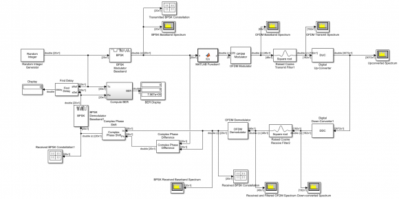
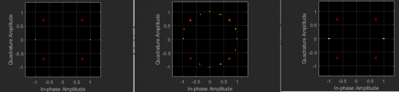
I am back with a question related to my OFDM Transceiver System that I am designing where I use DUC and DDC. I could get rid of the high BER problem. I realized that the problem was due to the phase error occuring between the transmitter and the receiver side as I saw the constellation diagram at the receiver rotating constantly. So to get rid of this, I obtained the phase difference between the transmitter and the receiver and I rotated the complex signal with the obtained phase error. However, I feel this is only an ideal method to get rid of the phase error. I read about the phase error compensation techniques but those are mostly when there is a noise in the channel. But in my case, I still haven't added any noise in the channel. I suspect the phase error is either because of the DUC and the DDC, or because of the pulse shaping filters that I used after OFDM modulator.
So I was wondering if anyone could tell me why is this phase error occuring even without a noisy channel, and what can I do to mitigate the phase error with some estimation.
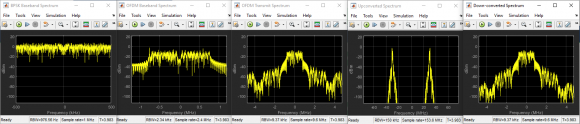
I have attached the screenshot of my system along with the waveforms obtained. Below are the specs -
Random Integer Generator Specs
Set Size - 2
Initial Seed - 37
Sample Time - 1/1e6
Samples per frame - 20
OFDM Modulator Specs
FFT length - 32
Number of guard bands - [6;5]
Insert DC Null - Checked
Cyclic Prefix Length - 16
Number of OFDM symbols - 1
Number of transmitted antennas - 1
Raised Cosine Transmit Filter Specs
Rolloff factor - 0.2
Filter span in symbols - 8
Output samplers per symbol - 4
Linear amplitude filter gain - 1
DIgital Up- Converter Specs
Interpolation factor - [2 8]
Minimum order filter design - Yes
Two-sided bandwitdth - 2.4 e6
Passband ripple - 0.05 dB
Stopband ripple - 90 dB
Center Frequency - 30e6
Input sample rate - 9.6e6
Digital Down-Converter Specs
Decimation factor - [8 2]
Minimum order filter design - Yes
Two-sided bandwitdth - 2.4 e6
Passband ripple - 0.05 dB
Stopband ripple - 90 dB
Center Frequency - 30e6
Input sample rate - 153.6e6
Thank you in advance!

It seems to me you are generating ofdm(using ifft) then this is upsampled to DUC and back downsampled through DDC then you do fft then check constellation.
If so one issue that can cause phase problem is that of filters group delay. you need to take account of group delay of various filters when trying to recover ofdm frame boundary. I mean you need to discard the delay section then do fft. In real systems time offset (also called cp offset) is used to shift the stream. This group delay has to be converted as appropriate at sample rate of fft at receiver. In short you need to discard the initial filters garbage.
Thank you sir for the reply. I have a question about what you said. You mentioned discarding the initial filters garbage. I do not understand this. Can u please elaborate it? I mean how do I discard the delay section before using the FFT? I just used the filters as a way to pulse shape the OFDM spectrum. Thank you!
Let me help with this ideal model. Play with it...it might answer a lot of questions. The resample functions remove initial filter delay but you can try other filters that don't.
-------------------------------------------------------------------------
clear; clc; close all;
%pkg load signal; %if Octave
%pkg load communications; %if Octave
nFFT = 2048; %fft size
nCar = 1200; %number of active carriers
alphabet = [-7,-5,-3,-1,1,3,5,7]*2^11;
QAM = complex(randsrc(nCar,1,alphabet),randsrc(nCar,1,alphabet));
fft_in = zeros(1,nFFT);
fft_in(2:nCar/2+1) = QAM(nCar/2+1:end);
fft_in(end-nCar/2+1:end) = QAM(1:nCar/2);
y = ifft(fft_in)*sqrt(2048);
y = resample(y,5,1); %upsample
tx_f = exp(j*2*pi*(0:length(y)-1)*.1);
y_up = tx_f.*y; %upconvert
Rx_f = exp(j*2*pi*(0:length(y_up)-1)*-.1);
y_dn = Rx_f.*y_up; %downconvert
y_dn = resample(y_dn,1,5); %downsample
Rx = fft(y_dn)/sqrt(2048);
plot(real(Rx),imag(Rx),'*');
Thank you so much sir for this simple yet amazing code. I see that you just upsample the ifft signal before up converting and then downsample after downconverting. Instead of using a pulse shaping filter, which has a linear phase response, you just upsampled the signal. This means, there won't be a phase difference in the process. I understand it now and will try to use this method in my system as well. Thank you!
But sir, I tried to do the same but I still get some phase error. This maybe because of the DUC and the DDC blocks, which is different than just simple up -conversion. The DUC and the DDC blocks contain CIC filters and compensators inside, which may not be in sync at the DUC and the DDC end. Maybe because of this I am still getting some phase error. The unfortunate thing is I cannot contol the filters inside. I can only specify the filter order, stopband and passband frequency requirements.
Resample matlab function is ideal i.e. it removes initial filter samples. In your design using CIC you should discard those first samples. You can check directly the input/output to cic using suitable signal e.g. a square waveform or sine waveform then discard a number of samples equal to delay of cic to get your signal as clean as input to cic. This is also needed at downsampling. Anywhere you use filtering. The overall system delay offset can be implemented in a single stream offseting at receiver. Or just experiment with offset for best result.
I see. Do you think finding the group delay of the cascaded filter response for the DUC and the DDC might do any help? Actually the method that you mentioned is not possible since I cannot access the CIC filters and compensators inside and in no way I can send a signal to check what delay the CIC filter gives me. I can only give an input to the DUC and check the signal at the output of the DUC and not near the CIC that is inside. In that case do you think I could do something by knowing the group delay? The group delay here shows 63.5 and is constant. Any idea on how to compensate this delay?
You need to apply exactly an offset equal to delay.
Below my code adjusted for actual filtering, see how delay can make difference of constellations. I am applying delay of 80 samples at Tx then Rx. Equally you can just apply delay of 160 at Rx
-------------------------------------------------------
clear; clc; close all;
%pkg load signal;
%pkg load communications;
nFFT = 2048; %fft size
nCar = 500; %number of active carriers
alphabet = [-7,-5,-3,-1,1,3,5,7]*2^11;
QAM = complex(randsrc(nCar,1,alphabet),randsrc(nCar,1,alphabet));
fft_in = zeros(1,nFFT);
fft_in(2:nCar/2+1) = QAM(nCar/2+1:end);
fft_in(end-nCar/2+1:end) = QAM(1:nCar/2);
y1 = ifft(fft_in)*sqrt(2048);
y1 = [y1, y1, y1];
y2 = upsample(y1,5); %insert zeros
h = fir1(160,600/2048*2/5+.005);
y3 = filter(h,1,y2);
yt = y3(1+80:end);
yt = yt(1:5*2048*2);
tx_f = exp(j*2*pi*(0:length(yt)-1)*.1);
y_up = tx_f.*yt;
Rx_f = exp(j*2*pi*(0:length(y_up)-1)*-.1);
y_dn = Rx_f.*y_up;
y_dn = filter(h,1,[y_dn,y_dn]);
y_dn = y_dn(1+80:5:end);
y_dn = y_dn(1:2048);
Rx = fft(y_dn);
plot(real(Rx),imag(Rx),'*');
Hello sir, sorry for the late reply. Regarding my system, I kind of fixed the problem but I do not know if it is a good way to fix it. So I was wondering if you could tell if my method is acceptable.
Actually, what I did was I simulated my system first for a known input signal and then obtaining the phase difference between the transmitter and the receiver. After knowing this phase error, I simulated my system with random data this time but I used the obtained phase error to complex-shift the received signal. Now I get zero BER without the channel and with AWGN channel of 12 dB, I get around 0.02 BER.
It is kind of similar to pilot based phase estimation right? Do you think this method is acceptable or is it again very ideal?
That is partly correct at least.
There are two issues with your ofdm based channel:
1) mixer phase (and frequency) must match between Tx & Rx
2) filtering delay must be offset. i.e. the rx fft must start from correct frame boundary of tx.
It could be by your work you have managed both points.
Yes sir, but here I haven't used mixer. Basically I want to build this system in an all-digital way and that is why I am using digital up and down converters and after the signal is up converted by a DUC I will assume that it will be sent to an RF sampling direct DAC and then receive the same using a RF sampling direct ADC. So here the use of mixer is removed. The only offset I was getting was from the DUC and the DDC since the CIC filters inside them have a linear phase response. But with this method that I mentioned, I could get rid of the phase error.
DUC implies mixer to upconvert to higher frequency. DDC reverses by mixing down to dc. I assume you are using mixers (digital may be)
Yes sir those two mixers we cannot ignore. Yes they are digital but I guess simulink implements with those mixers being already matched I guess.

Hello!
In simulation model it is possible to get phase delay of the path and compensate it. However, in real life your transmitter and receiver won't be coherent either way, so besides phase offset due to propagation delay there will be other sources of phase discrepancy. So in practical system people estimate phase rotation using pilot tones or training symbols in received signal, whose phases are known.
Hello sir!
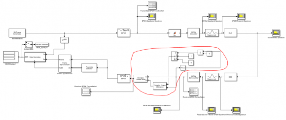
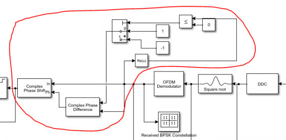
Thank you for replying my question. I understand that in real life we get rid of the phase error in a different way than the way I did. But actually I was trying to achieve wideband frequency hopping in my system and I wanted to propose a system that is all digital by using RF sampling direct ADCs. I am thinking of trying to implement it on a RFSoC so just wanted to show some results in simulation level for comparison as well. The system shown above is not the system that I am designing, it is just to test. However, I tried to modify the phase correction part by just taking the real portion of the signal that I receive, and depending on whether the real portion is a +ve or a -ve, I try to calculate the phase difference between a +1 or a -1 and then use the obtained error to phase shift the signal. I have attached the screenshot of what I did and I highlighted the part that I mentioned with red. I achieve correct constellation diagram. It is just that I do not know if this is acceptable or not. Once I add a channel I am sure I need to do many other things but without a channel, please let me know if it is a right thing to do or not.
Thank you!
I'm sorry, could not see anything in the picture, it was compressed too small.
From your explanation I can't get, how do you calculate the phase difference. If you know phase of sent signal, calculated phase of received signal, then their difference is yes, good way to compensate. One thing, this is done on per carrier basis in frequency domain, i.e. receiver knows expected signal and can calculate these differences for the whole bandwidth.
One thing to remember, if you do your compensation in frequency domain, then carrier next to DC will get phase shift of dPhi, next carrier will have twice 2dPhi and so on. In some systems like WiFi you don't have reference for the whole bandwidth, only few pilots, then you have to interpolate across the bandwidth.
May happen you're trying to compensate while still if time domain. In your idealized case that would definitely work. The only distortion your path introduces is delay, so that could be compensated.
Sir, my method of compensating the error is pretty simple. The signal that I send in the transmitter is just a BPSK signal right? So that means my signal is real and it is either a +1 or a -1. So at the receiver the signal that I receive will be a complex since it will also contain an imaginary part. So when I receive, I try to analyze the real part. If the real part of my received signal is a +ve number then I calculate the phase error with respect to +1 and when the real part is negative I measure the phase error with respect to -1. The error measured is in time domain by using correlation method. Once I obtain the error, I shift the signal by the same amount obtained. Below is a better image of my simple method.
Well, this is just how equalizer works - it finds compensating factor which turns received signal into expected one.
Keep in mind, you can't just blindly rely on incoming signal to see whether that is close to 1 or -1. Some day you change you filtering or other processing block and may happen your phase delay would be over one quadrant.
Yes sir I get that and that is why I am not getting the BER completely as zero. But do you think I can read any method which might give me better results? Right now my BER is around 0.3, which is poor.
0.3 in ideal conditions means something is very wrong.
Once again, I can't see how exactly you compensate your phase. It should be done per each carrier separately. As I wrote above, if carrier next to DC has phase delay of dPhi, then second carrier would have 2*dPhi, third one - 3*dPhi and so on. Because of finite precision calculations, and frequency selective effects in real life you can't estimate phase rotation at one carrier and then propagate it across whole bandwidth. Instead, you have to estimate phase error per carrier and apply compenasation per carrier as well. This work requires some known, non-arbitrary information to be present in you signal. It could be pilot tones comb, reference symbols and alike. Then at receiver side you will calculate phase errors using this a priori known info.
Be sure to use complex conjugate operations to calculate your compensation factors.
Actually sir, if I use the "complex phase difference" simulink block to calculate the difference and then use it to shift the signal, I get a zero BER. But since this method is ideal, and plus the channel is ideal. I was wondering if I could somehow get rid of the phase error without using any estimation techniques, because such techniques are mainly when you have a channel. I could very well use the techniques once I include channel.
Earlier, I was using the pulse shaping filters after the OFDM modulator but now I got rid of those filters by just upsampling my OFDM signal before using DUC to up-convert. But right now, I still get some phase error and this is because of the CIC filters and compensators inside the DUC and the DDC. Do you think if there is any method to get rid of any delay/phase error arising because of the filters inside the DUC and the DDC?


