


I read nice discussions on this forum about CIC filters and that's why I also joined. I am not expert in DSP. I am programmer and I need to write a CIC filter for a digital Signal.
Our signal has -3, -1, 1 and 3 as the values. It is on 53MHZ and it is very expensive to do measurements. So it should go to a lower frequency, for example 4MHZ. I read some Journal papers which seems CIC filters are good for this purpose but still I have issue to understand some simple stuff.
Now my questions:
1. How the decimations effect the intermediate frequency?
2. Should I take care of Phase? I have no idea how this can effect the Signal.
3. Can I do the algorithm on the numbers such as 3 or should I do it on the 8 bit of Zeros and Ones?
4. Should I separate the number of Inputs or should I do it continuously? it seems after some entrances the Output goes to high. Or Maybe I did that wrong.
5. Suppose that my signal is as follow. What is the output? Please mention the R,D and S in your measurements or write the whole table. Thanks in advance.
| 3 |
| 1 |
| 1 |
| 3 |
| 1 |
| 1 |
| 1 |
| 3 |
| 3 |
| 1 |
| -1 |
| 3 |
| -1 |
| 1 |
| 1 |
| -3 |
| -3 |
| 3 |
| 3 |
| 3 |
| 1 |
| 3 |
| -3 |
| -1 |
| 3 |
| 1 |
| 1 |
| 3 |
| 1 |
| 3 |
| 3 |
| -3 |
| -1 |
| 3 |
| 3 |

Hi Amin,
Take a look at this article if you have not already read it:
https://www.dsprelated.com/showarticle/1337.php
regards,
Neil

Hi, Thanks, I already read that one. It was good but not enough. Still had some issue to understand.

Thanks. I will contact you very soon.
I'm not an expert on digital communications systems but if your signal can only have four values then it appears to me that your signal may be "symbols" used in a four-level amplitude shift keyed (ASK) digital communications system. If I'm correct, I don't think it is possible to downsample (decimate) such a sequence of symbols without losing information. Of course I could be completely wrong because I know so little about the nature of your signal. How is your signal generated? What do your signal's four amplitude levels represent?

As you suggest Rick, it certainly looks like a 4 AM symbol sequence.
I'm guessing that the sample rate of the captured data is 53 MHz, but that the symbol rate is probably much lower. Hopefully less than 2 MHz if aminnoura hopes to recover the data.
It is a satellite data. I did the downsampling with a very simple method and it is working but the results are not satisfying. I read that probably CIC with compensation can do it better.
my 5c,
1. How the decimations effect the intermediate frequency?Decimation in general will give you the frequency if the frequency is less than half of the final sampling rate. the final sampling rate is the original sampling rate/decimation factor.
If the frequency is higher than the final sampling rate, the frequency will alias.
CIC in particular does LPF and decimation as a combo. the LPF will act as the anti aliasing filter. CIC alone will not give you ideal LPF. if you want to make it close to ideal, then you need to add CFIR to compensate the non-flatness.
2. Should I take care of Phase? I have no idea how this can effect the Signal.
CIC is an FIR operation. so Phase information won't get altered. So, even after CIC, you can get the relative phase information. for example, if you have a I/Q mixer, followed by two CIC, then the phase information in after the CIC will be valid.
3. Can I do the algorithm on the numbers such as 3 or should I do it on the 8 bit of Zeros and Ones?You should treat the numbers are 2's complement. the accumulator/register width decides the SNR.
4. Should I separate the number of Inputs or should I do it continuously? it seems after some entrances the Output goes to high. Or Maybe I did that wrong.
That is very important. the interim value after acc really go high after initial iterations. However, the output of differtiator will get the value back to the range. if you want to emulate that in excel or MATLAB which natively uses float, you should emulate the 2's int complement operation.
int cic_int(int *pX, int *pY, int r, int n, int BlockSize)
{
 static int S[MAX_STAGES] = {0};
 int out = 0;
 static int count = 0;
 int countOut = 0;
 for (int i = 0; i < BlockSize; i++)
 {
        count++;
        S[1] += pX[i];
        for (int j = 1; j < n; j++) {
            S[j+1] += S[j];
        }
        if (count%r == 0)
        {
            static int compOut[MAX_STAGES];
            static int delayBuff[MAX_STAGES];

            delayBuff[1] = S[n-1]; // inp to the first comb
            for (int j = 1; j <= n; j++) {
                // using  matlab indexing. j = 0 is unused
                delayBuff[j+1] = delayBuff[j] - compOut[j];
                compOut[j] = delayBuff[j];
            }

            pY[countOut++] = delayBuff[n];
        }
 }
 return 0;
}
an implementation which uses 32-bit acc with int operation is attached.
The static array S[] will have wide range values with heavy DC. however, the delayBuff[] after Diff will bring the value back to normal range !
I will try it for sure and will let you know how it is helping me. Thank you a lot.
Thanks a lot. It is a good answer.
1. Yes I know that I also Need a compensation but I am still stuck in the CIC implementation.
2. I did not understand your answer to number 3. Can you kindly explain a little bit more.
3. Can you show me on a table what is happening if I want to process my given input. what would be the output. For example in 5 stages with decimation factor equal to 8 and delay equal to 1.
to get the expected result one needs to perform the CIC add and sub as int operations. you won't get he expected results if you do the operations with float.
to emulate the acc, i did the following in matlab.
this code i can emulate any acc width. instead of coding c = a+b; use, c = obj.math.sub(a, b);
the results with your input and another (sin) input is attached. 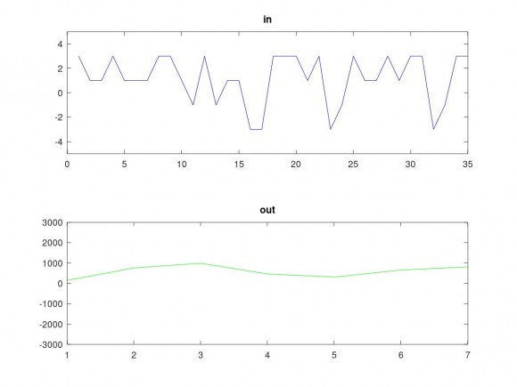
methods %(Static)
       function obj = my_math(bits)  % my_math class constructor
           obj.bits = bits;
           obj.minv = -2^bits;
           obj.maxv = 2^bits-1;
       end
       function s = wrap(obj,sum)
           s = sum;
                if(sum > obj.maxv)
                    s = obj.minv + s-(obj.maxv);
                end
                if(sum < obj.minv)
                    dd = abs(s)-abs(obj.minv);
                    s = obj.maxv - dd;
                end
       end
      function s = add(obj, a, b)
                s = obj.wrap(a+b);


      end
      function s = sub(obj, a, b)

                s = obj.wrap(a-b);
      end
    end
output for your supplied data :
[ 148 759 990 461 311 655 811]
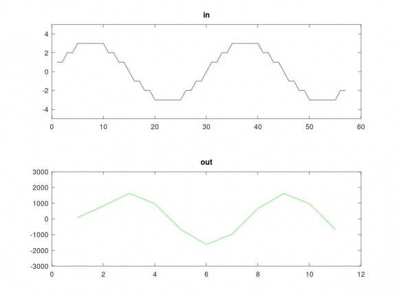
output for
x = round(3*sin(2*pi*[1:57]/30));
[86 827 1627 961 -665 -1626 -961 665 1626 961 -665]


