


Calculating cross-correlation with Walsh-Hadamard transform
I am trying to implement MLS method of measuring impulse responses. There is an article describing the method: http://www.commsp.ee.ic.ac.uk/~mrt102/projects/mls.... As I understand, to get an impulse response of a system I need to calculate cross-calculation of input signal - MLS and output signal of a system.
I tried to do measurements on simple lowpass RC-filter. The result I get is strange, it is a noisy signal that does not look like lowpass filter signal response. I tried to use convolution and circular correlation but it didn't help.
I suspect the problem is related with calculation methods. I calculate correlation using the convolution theorem that allows to calculate convolution using Fourier transforms of signals. But, the article describes Walsh-Hadamard transform to use in the method.
Also I checked the form of MLS, the generated signal is correct, but I am not sure should it be periodic or not.
My questions are:
Can I get wrong results because I don't use Walsh-Hadamard transform during calculations?
Could you, please, give a sample of code in Matlab or Python that calculate correlation using Walsh-Hadamard transform?
Can there be other sources of problems, for example, distortion related with periodicity of MLS-signal?
Thank you in advance.
P.S. I can show screnshots of wrong impulse responses I got if it is required.

An MLS by definition is not periodic. The instructions in that paper are 1) Generate an MLS sequence at least as long as the impulse response and 2) Stimulate the system with at least two successive MLS bursts. I assume the sequences are different, which implies you either want an MLS at least twice as long as you need or it has to be shifted some random amount.
What it does not say is what the pulse width is on the sequence. If the pulse width of a single pulse is longer than the impulse response, this really can't work at all. It implies the pulse width is much shorter than the impulse response, but that's not clearly stated.
So first, hit your RC filter with a single fast pulse and just measure the impulse response. Then figure out how to create an MLS that fits the length, and measure what it does. I think seeing this in the time domain will help a lot in understanding the point of the paper. Then try shifting the MLS vs creating a much longer version which can be used multiple times. But if the point is that the MLS is supposed to repeat - then it really has to be pretty short and I don't see the point of multiple measurements as described. You should get the same thing every time.
The point is - play with it. Look at what the system does with a real impulse and compare it with the MLS. Then work your way through the paper one step at a time. I don't see the point of the method, but you should be able to figure out all the details by carefully examining each step of the way.

 Hi forthan,
to answer your questions:
"Can I get wrong results because I don't use Walsh-Hadamard transform during calculations?"
--> It is not necessary to use Walsh-Hadamard transform.
"Can there be other sources of problems, for example, distortion related with periodicity of MLS-signal?"
--> There are problems with MLS signals when used as channel sounders, however, that is probably not your problem.
Check that you are using oversampling. Dr. harris recommended 4x oversampling. You simulation may appear correct because you have no frequency offset between your TX and RX but your actual ADC may have an offset.
Here is some Matlab code for a simple sounder using PN sequences. Depending on what channel you are trying to measure (for example, Room Impulse Response with T60, optical, etc) a chirp or complementary sequence may be better suited for your application.
%% Jay Cordaro
%%
%% Simple PN Sounder
%% April 10, 2021
%%%%%%%%%%%%%%%%%%%%%%
%% generate a PN Seq
h1=commsrc.pn('GenPoly',[15 1 0], ...
'InitialStates', [ zeros(1,14) 1]);
%% we want it to repeat 3x to make it a periodic
% sequence
set(h1, 'NumBitsOut', 3*(2^15-1));
%% make it +/- 1
scrbits=2*generate(h1)-1;
transmit_seq=scrbits';
%% upsample it
upsample_rate=4;
src1=kron([transmit_seq], [1 zeros(1,upsample_rate-1)]);
%% create a replica to correlate against at receiver. It correlates at
% the upsample rate
corr_sig=rectpulse(transmit_seq(1:2^15-1),upsample_rate);
%% Create simple 4th order butterworth filter as our channel
% then convolve it with the transmitted seq. to make or rcvd sequence
fs=1;
LPF_cutoff=.0625;
[a_lpf, b_lpf]=butter(4,(2*LPF_cutoff)/fs);
rcv_sig=filter(a_lpf,b_lpf,src1);
%% convolve the received signal with the flipped version of our
% channel to get our chimp (Channel Impulse Response)
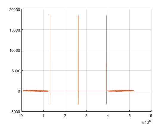
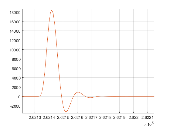
chimp=conv(rcv_sig,flip(corr_sig));
plot(chimp)
%% for the heck of it, do circular convolution
figure(2)
clf
hold on
grid on
plot(cconv(rcv_sig,corr_sig([1 end:-1:2]),length(corr_sig)+length(rcv_sig)))
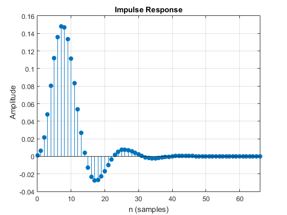
%% check the chimpfigure(3)
impz(a_lpf,b_lpf)


MLS through DAC/ADC is just pseudo-random sequence of +1/-1 and as such it is one case of BPSK channel. So how come it can be used to get system response. Apart from aiming at some frequency levelling it is not an efficient way. what you (or paper) are saying : inject input with flat top spectrum and see output in frequency domain. That is ok but is not accurate enough as it is not that flat.
For classic BPSK system you need to shape and upsample by 2 minimum for pulse shaping and getting rid off sharp corners.


