


Power Spectral Density PSD° of OFDM signals
Hello guys,
I'm quite new in OFDM techniques and i would really appreciate if someone could help me. Here is my problem. Assume i have a binary stream converted into complex values X(k) via the QPSK constellation. With those complex values, i want to generate an OFDM signal using the IFFT formulation; I also want to control the amplitude of the signal according to the DSP using the paramater A(k), k being the subcarrier. For n being the time sample, N the number of samples/subcarriers, I generate the OFDM signal as follows:
x(n) = (1/ N) * sum(A(k) * X(k).* exp(1j * 2 * pi * k * n / N).
If the DSP at a given subcarrier is greater than a certain threshold, I apply the parameter A(k) to reduce it.
My problem is I'm not sure how to determine the DSP at each subcarrier. I'm currently using this expression :
DSP(k) = 1/N * ||X(k)||^2.
But for me it seems like the DSP would be the same regardless the operating frequency band. The only thing that may cause a difference is the constellation used to detremine the X(k) : BPSK, QPSK, 16-QAM, ... What do you think about it? Am I rigth to calculate the DSP using this expression. Is there another expression that can be sused?
Thank you so much for your help!

I think you're typing DSP when you mean psd, but that's okay. ;)
Regardless, you can set the amplitude of each subcarrier however you want, to make them all the same or vary them to compensate for channel conditions. Taking the magnitude as you are suggesting is certainly a reasonable way to do it.
Thank you so much!
Yeah i actually meant PSD not DSP which is the french word :)
Ok then I'll keep using this method for now. I will use a power amplifier after the IFFT/DAC for the purpose of dealing with channel conditions but I have a PSD mask that I must comply with. So I wonder if the power amplifier will not change the PSD set at the constellation level.
Parseval's theorem says that power is maintained across domains, so if you increase or decrease power in one domain, the same thing happens in the other, if that's what you mean.
Changing power across various subcarriers can change the peak-to-average power ratio in the time domain, though, and that can be important at the power amplifier to prevent clipping.
Oh great thanks! So if the power of the transmitted signal must be maintained at a certain level, the PSD set at the subcarrier must be even lower than that since the power amplifier will increase that power afterwards, am I right?
For now, I've been dealing with the PAPR by adding a phase shift on the subcarriers. I guess the PSD set will also help dealing with that.

If you want control per sub-carrier then you do that at constellation level. Once ifft is done it maintains the relative power among subcarriers as it is frame base. Though you can control the power transfer between ifft input symbol and its output symbol.
Thank you for the answer!
Yeah i want a control per subcarrier at first but if I manage to maintain the power level on each subcarrier below the threshold (let's say -50dBm), the time domain signal will then be amplified with a power amplifier. I assume this will lead to a modification of the power levels that have been set with the parameter A(k).
I'm sorry if my questions are silly, i'm quite new at this. If there are books (pdf) you can recommand for a beginner, it'd be of great help.
Thank you!

Hello,
I have created a simulink model that can be used to answer your questions very easily and clearly.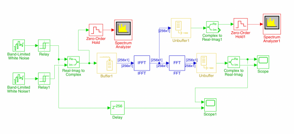
A complex signal corresponding to QPSK is formed from two random binary sequences. The PSD in dBW/Hz is displayed on the Spectrum Analyzer. The binary data is generated at 1000 Hz and the spectrum is displayed in the range -5000 Hz to 5000 Hz (fig. 1).
Data blocks of 256 complex values are formed with the buffer block. From this, with an inverse FFT, the two real signals that have to be transmitted are obtained. The PSD spectrum of one of these real signals is then displayed in the same frequency range on the Spectrum Analyzer 1 block.
At the receiver, the original I and Q are then obtained again with an FFT.
The I signal from the transmitter and the I signal from the receiver are compared on the Scope 1 block (fig. 2).
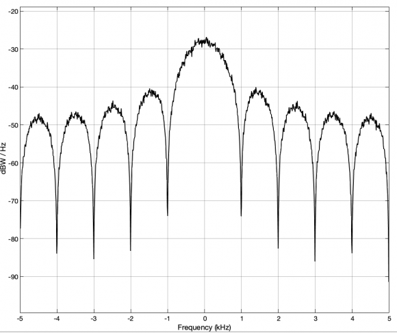
Fig. 1
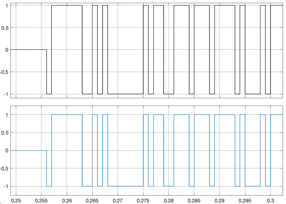
Fig. 2
The model is with MATLAB 2021a created. The File is:
Thank you for this example.
Unfortunately, I don't have Simulink with my Matlab license to run your model. However, I don't get the mathematics underlying the result displayed on fig.1 . If the PSD on a subcarrier is obtained using PSD(k) = 1/N * ||X(k)||^2, X(k) being the complex value of the constellation, shouldn't we have the same value of PSD on all subcarriers since the QPSK constellation is +(-)1 +(-)j? Or am I missing something on the derivation of the PSD?
I understand. But since the Xk values at the transmitter come from the constellation, it should be the same if I apply the formula directly to the values coming from the constellation (assuming that xi + j*xq = IFFT(Xk) then Xk = FFT(xi +j*xq) as in your example).
Here is the code that I used to simulate the IFFT/FFT to generate an OFDM symbol.
Thus, instead of using FFT(xi + j*xq) to derive the PSD, i have directly used the Xk symbols from the QPSK constellation. I have tested this second matlab code DSP_OFDM.m and I've added in the formula of the PSD a division by the appropriate frequency to have a variation of the PSD. Maybe I'm missing something, but without that division, the PSD is a constant for the QPSK modulation.
PS : I hope I'm not taking too much of your time. I really appreciate your help and explanations. Thank you
since you have matlab(or Octave) then you can experiment with ifft as follows:
%%%%%%%%%%%%%%%%%%%%%%%%%
x = zeros(1,1024);
x(78) = complex(.2,-.6); %populate one subcarrier as example
y = ifft(x,1024);
figure;plot(real(y)); %Time domain
Fs = 1;
fx = (0:1/1024:1-1/1024)*Fs; %frequency axis
figure;plot(fx,abs(fft(y))); %frequency domain
%%%%%%%%%%%%%%%%%%%%%%%%%%


