


Is there any way to prevent Deconvolution?
Hello,
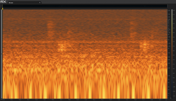
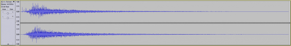
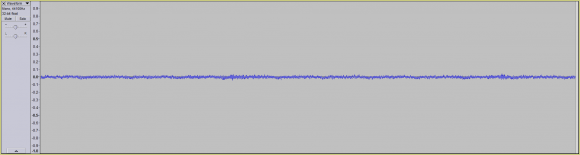
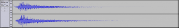
Assuming you were only provided a dry signal:

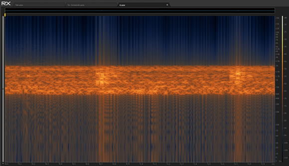
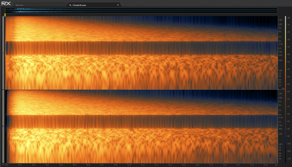
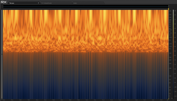
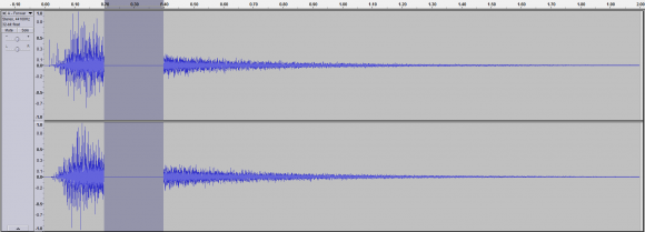
...and wet signal (with reverb applied to it via convolution reverb):

...is there anything that I could do to my dry signal or impulse response (IR), to prevent you or anyone else from accurately deriving my IR through Deconvolution?
Note: If there is something that could be done, it must be done to both the dry signal and IR before performing any convolution, not after.
Thank you,
Nelson

Hi Nelson,
I think what you are looking for is to remove a band of frequencies in the dry signal. This will result in the same band of frequencies having a value of zero in the wet signal. Since these signals give you no information about the system's frequency response in this band, one cannot calculate the impulse response that was used. In other words, an infinite number of impulse responses could have been used to convert this particular dry signal into this particular wet signal.
Regards,
Steve
Hello Steve,
I'm not certain if this will work (though I could be wrong).
Let's take the following example:
Assuming we start with the following dry signal:

...with the following Spectrogram output:
If we were to remove a specific frequency band (ex. everything outside of 500 Hz to 2 Khz), we'd arrive at following new dry signal:
...with the following Spectrogram output:
If we were then to use our IR:

...on our dry signal (applying convolution reverb), we'd arrive at a signal which doesn't take into effect the IR's frequency information outside of 500 Hz - 2 Khz, correct?
However, can I assume that a third party, who was only given the dry signal (with frequency material removal outside of 500 Hz - 2 Khz), and wet signal, they could at the very least derive the IR signal information in between 500 Hz and 2 Khz?
In other words, if the following Spectrogram output:

...pertains to our IR, the third party (who doesn't have access to the IR), should at the very least be able to derive the parts of the IR in-between 500 Hz and 2 Khz (highlighted in green):
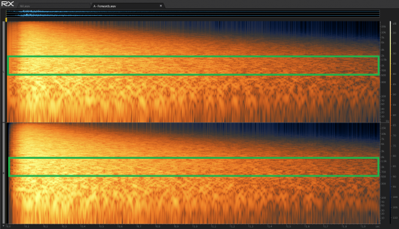
...which acted upon our dry noise signal?
Thank you,
Nelson
Hi Nelson
Yes, all correct. The adversary could look at the frequency spectra of the dry and wet signals, note that there was a gap in the information, and try to guess or interpolate the missing sections. However, after taking the Inverse Fourier Transform, the impulse response they obtain will probably be very different in appearance than the correct one. Even small changes of this type in the frequency domain can cause large distortions in the time domain signal.
Just to be clear, the impulse response is a time domain signal. That is, the wet signal is equal to the dry signal convolved with the impulse response. The Fourier Transform of the impulse response is the frequency response. In your text you say "the following impulse response," but then show what appears to be the the frequency response.
Regards,
Steve
Hello Steve,
My apologies about the terminology mixup, as my background in DSP is severely lacking.
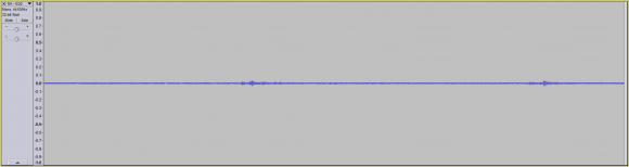
That being said, can I assume that if we had the following time domain signal:

...with the following Spectrogram output:

That if removed a specific frequency band from our time domain signal (ex. 500 Hz to 2 Khz):
...resulting in the following time domain signal waveform:
...that our attacker would at the very least be able to exactly derive the subtraction of both our original time domain signal and our new time domain signal (with frequency data removed between 500 Hz - 2 Khz)?
In other words:
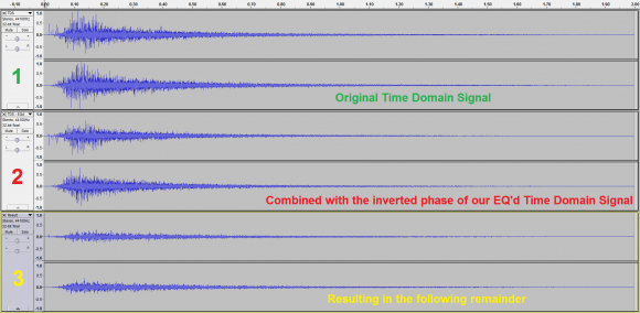
Waveform 1 - Our original time domain signal
+
Waveform 2 - Inverted phase (to perform a subtraction) of our EQ'd time domain signal (missing frequency information between 500 Hz and 2 Khz)
=
Waveform 3
So the question is, would our attacker be able to exactly derive waveform 3, or would the distortions you were referring to in the time domain signal, result in a different waveform 3 (due to things like approximation errors)?
Thank you for all your help,
Nelson
Hi Nelson,
Glad to help; everyone starts out at some point. Your last post is mixing up the concepts of time domain, frequency spectra, and spectrogram. I think you are going to have to learn more about these basics before you can answer your question. Here's some free material: www.DSPguide.com/pdfbook.htm. You might start with chapter 9 and 22. Feel free to e-mail me with questions: Steve dot Smith at Tek84 dot com.
Good Luck!
Steve
Hello Steve,
Thank you for all your help (including the reading material on DSP).
Regards,
Nelson
Here is a guess. Invert the spectrum.
Hello John,
When you say to invert the spectrum (I assume you're referring to the frequency spectrum), are you referring to both the IR and dry signal?
Also, is a spectrum inversion similar to a phase inversion (like flipping the waveform vertically)?
Thank you,
Nelson
Spectrum inversion means converting a low frequency component to a high frequency component and vice-versa. You do this by multiplying your signal by a CW "carrier" that is near the high end of your spectrum. This will result in an upper and lower sideband. You can outphase or filter the undesired sideband. In the remaining sideband, frequencies that were very high will be very near the carrier, and thus will be relatively low. Frequencies in the original signal are far away from the carrier and will be very high. An inverted spectrum is unintelligible to an observer that is not knowledgeable about the process.
Hello John
Though I don't completely understand all the steps involved in your spectrum inversion (I apologize for that), allow me to use a simple example to illustrate my current understanding.
Assuming we started off with an audio signal with only mid to low-end frequency data:
...if we were to perform a frequency inversion on our audio signal, resulting in the following frequency data:
...ultimately, all we'd have would be a different audio signal, correct?
That being said, if we then performed our convolution on the our new audio signal (with its frequency inverted) and gave some other party the dry frequency-inverted audio signal and the convoluted audio signal, I don't see how the other party would be prevented from determining the IR.
In other words, let's say there are two parties: Alice and Eve.
Alice has access to the dry signal, wet signal and IR.
Eve only has access to the dry signal and wet signal.
Assuming Alice:
1. Inverted the frequency of her dry signal.
2. Ran her frequency inverted dry signal through her IR, resulting in her wet signal.
3. Gave both her dry (frequency-inverted signal) to Eve.
4. Gave her wet signal to Eve.
I'd think it'd still be possible for Eve to figure out Alice's IR.
That being said, there could be something I'm misunderstanding.
Any help or further clarification would be greatly appreciated.
Thank you,
Nelson

I'm not sure what you mean by doing something to the "dry signal". If you did that then what happens to the reference? It seems like there's something missing here. It sounds like a desire for encryption. It certainly asks for masking the impulse response (IR), right?
One approach would be to make the impulse response complicated. Complications might include having elements close together, random sign reversals and temporal changes. What if the impulse response is a pseudo random sequence that changes?
Maybe a bit more information would help.
Hello Fred,
My apologies for the ambiguities in my description (as my knowledge in DSP is quite limited).
This is what I mean, let's say you had the following waveform (aka our dry signal):
...and the following impulse response (IR):

Let's say we used some convolution reverb software / plugin:
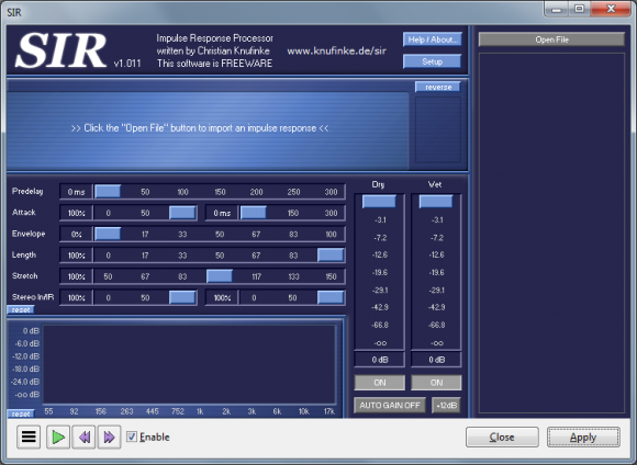
...to process our waveform using our IR.
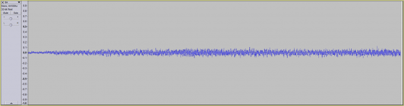
Using such software would result in the following waveform (aka our wet signal):
So my question is this, if you only the dry signal and wet signal (but not the IR), is there something you could do to the dry signal (and possibly IR), to make it impossible for someone to derive the IR?
Thank you also for suggestions (including the the addition of random numbers / phenomena). That being said, I'm not certain that would work as mathematically, it would seem trivial to derive the IR (but I could be mistaken).
Thank you,
Nelson
OK. Well, I understand it better now. Thanks.
Let me play this back:
Dry Signal: S1
Impulse response: R1
Convolve S1*R1 = S2
Wet Signal: Deconvolve S2 using R1 = S3
If S3 is a perfect deconvolution using R1 then all that's left is S1.
So S3=S1 and there can't be any notion of what R1 had been.
What did I miss? Well, for starters, from the plots, S1<>S3 so there must be *something*.
Hello Fred,
During the Deconvolution phase, you do not have access to R1.
Let's assume there are two parties:
Alice has access to S1, S2 and R1.
Eve only has access to S1 and S2.
So the question is, can Eve figure out R1 through the use of Deconvolution, if all she has access to is S1 and S2?
Currently, the answer is yes (as Deconvolution is mathematically trivial).
However, I'm trying to see if there's some special processing I could do to S1 (and/or to R1), so that the Deconvolution process is either impossible or far more difficult for Eve.
Note: This "special processing" must occur before any convolution has taken place, so that Alice and Eve both have access to the same S1 and S2.
Thank you,
Nelson
Ah! OK. I'm a bit more used to physical systems for R1 or simulators of the same.
If you have the ability to change S1 AND R1 then I should think that you have a lot of flexibility.
JOS says "divide by the frequency response". I think that means "divide the Fourier Transform of S1*R1 by the Fourier Transform of S1". (And not by the Fourier Transform of R1 as is the more normal case for deconvolution). That would be a common way to deconvolve an impulse response - as you called it.
But, since you have so much flexibility, perhaps you could re-frame the question: "How can I start with two signals / sequences S1 and R1 that will be convolved AND make it such that the deconvolution removing S1, leading to the extraction of R1 is difficult?"
S1*R1 = S2
F(S1)xF(R1) = F(S2)
F(S2)/F(S1) = F(R1) > IF(F(R1)) = R1
So, it appears that you want F(S1) to be full of zeros as one approach.
If F(R1) has zeros generally opposite the locations of the zeros of F(S1) then S2 would not have much energy. So likely not practical.
What if F(R1) has zeros generally matching the locations of the zeros of F(S1)? That sounds nasty but I've not worked it out...
.
Hello Fred,
Thank you for the explanation.
Just to be certain that I understand what you mean.
When you say, full of zeros, do you mean missing frequency information?
In other words, if we had the following time domain signal:
...with the following Spectrogram output:

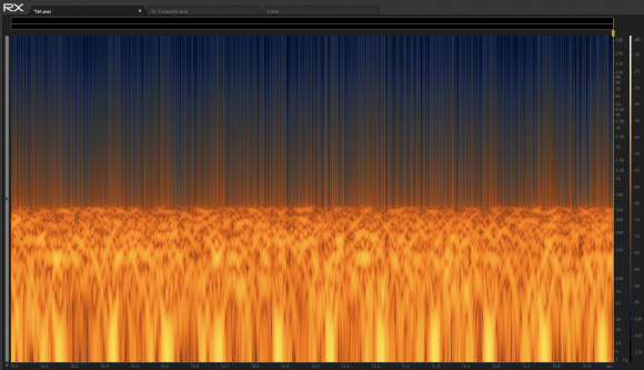
...and we removed a certain frequency band (ex. 500 Hz - 2 Khz), resulting in the following time domain signal:

...with the following Spectrogram output:

...that the gaps in our Spectrogram output, would be akin to the zeros you're referring to?
Also if F(R1) and F(S1) have zeros in the same frequency band, then I assume all that would happen is that during our convolution phase, the audio data pertaining to the missing frequency bands would not be taken into account during our convolution, correct?
Thank you for all your help,
Nelson
This is the first time I've noticed "audio data". I thought that S1 was something you could manipulate...??
I see temporal plots that look like radar or sonar.
I see these spectrograms which suggest that there's a signal for a while and then it's switched off for an interval. Is that right?
As I have been envisioning this:
There is an "impulse response" of a channel R1 and it is of finite duration - at least practically speaking.
There is an input signal S1 that has some finite length .. but maybe not. At least some finite record of it.
There is an output signal S3=S1*R1 which has the same temporal extent at least as long as S1 - so maybe infinite extent with a limited record.
You know what all of them are.
Someone else only knows S1 and S3 and not R1.
You want to protect R1 from "identification".
So, there seems no way to zero out temporal bands in the spectrogram. Those ARE temporal bands, right?
My suggestion was to zero out frequency bands, not temporal bands.
Or, perhaps to have lots of zeros in frequency in R1 and in S1 (if you can as you'd suggested). They could be dispersed in frequency and not just in bands. The only idea was to make deconvolution more difficult.
But, philosophically, imagine this:
If S1 has valuable information then zeroing out parts of it via R1 would seem to be counterproductive.
If S1 can be constructed to have zero values in frequency then that may be an approach but I don't see how it helps all that much because you would effectively be dividing F(S3) by F(R1) and NOT with F(S1).
If you can construct R1 with zeros such that it only blocks unneeded or redundant parts of S1; and yet, S1 does have those redundant parts nonzero, then you may be onto something. I don't know.
Hello Fred,
I'll have to think about this a bit more.
That being said, I greatly appreciate all your help.
Nelson

Lot's of 0s around the unit circle in the transfer function :-)
Non-minimum-phase 0s make it a bit harder, but you can still simply Fourier transform, divide by the frequency response, and inverse Fourier transform
Hello JOS,
Thank you for suggestion.
That being said, can I assume that through the use of 0's (in the IR I presume - see below):
...that a divide by 0 is non-issue (during the deconvolution phase)?
In other words, a divide by 0 (in mathematics or programming), is not allowed / leads to a runtime error.
However, in audio, I'd assume it's just ignored.
Thank you,
Nelson


