


Fraction saving and limit cycles in fixed-point IIR biquad implementation
From reading through fixed-point IIR implementation posts on these forums, it is my understanding that fraction saving squashes limit cycles. I implemented pretty much verbatim the fraction-saving scheme from here: https://dsp.stackexchange.com/questions/21792/best... in 16-bit fixed point, but it doesn't accomplish what I thought it would.
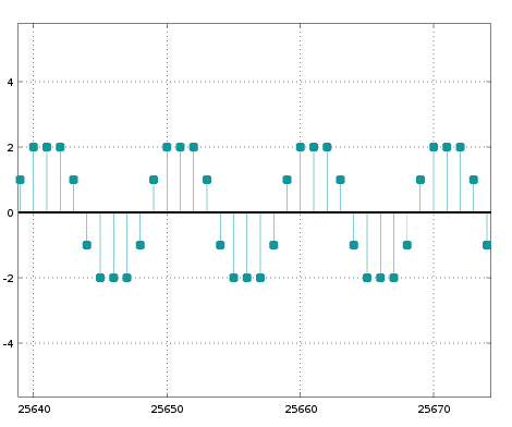
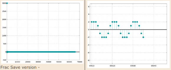
When I input a scaled-up impulse to my biquad section, the output does go into permanent oscillation even with fraction saving implemented. The following plot is the output of the first biquad, sos1:
The impulse response output of both the biquad sections comprising my 4th order filter shows an even more unexpected envelope on the oscillation:
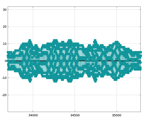
What's more, the amplitude of the oscillation appears to depend nonlinearly on the amplitude of the initial impulse. The outputs above were for an impulse of amplitude 30000. These plots change completely if the amplitude of the impulse is changed.
Is my understanding incorrect? Doesn't fraction saving magically result in impulse output of fixed-point IIR biquads converging to zero? Do other factors matter, like Q of the filter? The filter I'm experimenting with has poles almost touching the unit circle (magnitude 0.99981). Quantized coeffs improve this slightly, with a quantized magnitude of 0.99979.
Are there other considerations involved in the design of high-Q fixed point filters?

Many years ago, I was trying to implement an IIR high-pass filter in audio-like frequency range: Fs=48kS/s, Fcut=1.5Hz (HP), 6th-order butterworth.
The filter seemed to work but always after a long time (speaking of some 20min !), the output signal started to get weird and faded away, never recovering without reset.
I learned from that experience, that (especially HP) IIR-filters are very critical, if you don't pay very much attention to the precision of coefficients and of your signal processing width.
How I overcame failing of the filter:
- increased signal processing width to 26bit (don't ask me why this number, I don't remember)
- increased width of coefficients to 24bit
- width of incoming signal was not critical (16bit)
- Calculating the filter coefficients using Matlab was misleading!
After discussion with Mathworks developer I decided to drop that way, because the underlying calculation precision of Matlab was not high enough to calculate the coefficients precisely enough.
Scilab was slightly better (enough for me) - I calculated them manually for verification using Excel :-) - The internal stability checker of Matlab failed (had a flaw, which was later corrected).
- I had to learn, that I cannot first calculate TF(1) parameters and then convert them to SOS structure values because of the internal data representation losing too much of the precision.
I had no problems with LowPass filters, only with HighPass.
That was my learned lesson:
If I have to implement HP- or BPF with Fs/Fcut>1000, expect trouble - everywhere!
Maybe it's too off-topic, but could be a helpful hint...
Thanks @bholzmayer. 20 minutes for the problem to manifest, wow! This is my first foray into fixed-point IIR, and I gotta say, I'm astonished at the extent of the rabbit-hole. Had no idea that various rounding/truncating schemes could cause such dramatic changes in behavior. Btw by "signal processing width", do you mean the width of the accumulators? Wouldn't they need to be even wider than 26 bits though?
In my case, it is not fs/fc that is abnormally large, that ratio in my case is only about 9, but the filter is a peaking filter with very high Q. I got the coefficients through Octave via the ellip function.
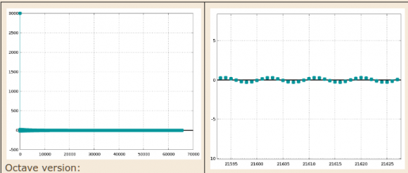
Perversely, straight-truncation of the accumulator (without Fraction Saving) does enable the impulse response to converge to 0!
I have not yet tried wider fixed-point widths. The eventual implementation is slated for an FPGA which has 18-bit multipliers, hence my desire to test with 16 bits (can only get better in an 18-bit implementation), but I think wider multiplies are possible by jumping through hoops.I suppose I'll either have to bite that bullet, or relax the Q of the filter.
High Q ends up with the same problem as a high Fs/Fcut in HPF.
Therefore my guess is that your issue is not at first limit cycling (maybe later ;-), but the described precision issue.
Problem with 16bit-coefficients is that stupidly rounding every value leads to big relative coefficient errors. An example with 5bit-coefficients:
a1=0.4
a2=0.16
sigValue@a1=0.16 while sigValue@a2=-0.4:
eventually stupid rounding gives a1=6, a2=3.
Applying the signal values and calculating sig*a1+sig*a2 => 3*6-6*3=0
If you would round both coeffs upwards giving a1=7,a2=3 => 3*7-6*3=3
Rounding both downwards giving a1=6,a2=2 => 3*6-6*2=6
As you see, in this case what I call "stupid" rounding gives a 0 here while the probably better value might be between 3..6.
You will face this sort of errors which cause most problems.
So, find a rounding method which gives the best overall result if you compare your resulting fixed point coefficients with the floating point.
If it comes to FPGA implementation, it's quite easy there to implement wider multiplier. Most FPGA IDEs provide libraries/cores for wider multipliers, which you could use as a starting point. If it works, then reduce coefficient/multiplier width as much as you want always comparing results.
And: you're right, when I was experimenting with 40bit wide multipliers, which gave good results. Reducing width to 26bit was possible, but:
less ressources cost more brain investment, and can come VERY expensive :)


