


Inductors
An inductor can be made physically using a coil of wire, and it
stores magnetic flux when a current flows through it. Figure E.2
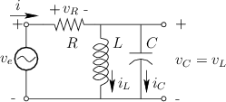
shows a circuit in which a resistor ![]() is in series with the parallel
combination of a capacitor
is in series with the parallel
combination of a capacitor ![]() and inductor
and inductor ![]() .
.
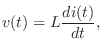
The defining equation of an inductor ![]() is
is
where
where
Taking the Laplace transform of both sides gives
Assuming a zero initial current in the inductor at time 0, we have
Mechanical Equivalent of an Inductor is a Mass
The mechanical analog of an inductor is a mass. The voltage
![]() across an inductor
across an inductor ![]() corresponds to the force
corresponds to the force ![]() used to
accelerate a mass
used to
accelerate a mass ![]() . The current
. The current ![]() through in the inductor
corresponds to the velocity
through in the inductor
corresponds to the velocity
![]() of the mass. Thus,
Eq.
of the mass. Thus,
Eq.![]() (E.4) corresponds to Newton's second law for an ideal mass:
(E.4) corresponds to Newton's second law for an ideal mass:
From the defining equation ![]() for an inductor [Eq.
for an inductor [Eq.![]() (E.3)], we
see that the stored magnetic flux in an inductor is analogous to mass
times velocity, or momentum. In other words, magnetic flux may
be regarded as electric-charge momentum.
(E.3)], we
see that the stored magnetic flux in an inductor is analogous to mass
times velocity, or momentum. In other words, magnetic flux may
be regarded as electric-charge momentum.
Next Section:
RC Filter Analysis
Previous Section:
Capacitors


