


Zero-Phase Filters
(Even Impulse Responses)
A zero-phase filter is a special case of a linear-phase filter
in which the phase slope is ![]() . The real impulse response
. The real impulse response
![]() of a zero-phase filter is even.11.1 That is, it satisfies
of a zero-phase filter is even.11.1 That is, it satisfies
A zero-phase filter cannot be causal (except in the trivial
case when the filter is a constant scale factor
![]() ).
However, in many ``off-line'' applications, such as when filtering a
sound file on a computer disk, causality is not a requirement, and
zero-phase filters are often preferred.
).
However, in many ``off-line'' applications, such as when filtering a
sound file on a computer disk, causality is not a requirement, and
zero-phase filters are often preferred.
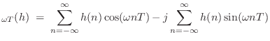
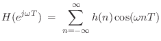
It is a well known Fourier symmetry that real, even signals have real, even Fourier transforms [84]. Therefore,
This follows immediately from writing the DTFT of
A real frequency response has phase zero when it is positive, and
phase ![]() when it is negative. Therefore, we define
a zero-phase filter as follows:
when it is negative. Therefore, we define
a zero-phase filter as follows:

Recall from §7.5.2 that a passband is defined as a
frequency band that is ``passed'' by the filter, i.e., the filter is
not designed to minimize signal amplitude in the band. For example,
in a lowpass filter with cut-off frequency ![]() rad/s, the
passband is
rad/s, the
passband is
![]() .
.
 -Phase Filters
Under our definition, a zero-phase filter always has a real, even
impulse response [
![]() ], but not every real, even, impulse
response is a zero-phase filter. For example, if
], but not every real, even, impulse
response is a zero-phase filter. For example, if ![]() is zero
phase, then
is zero
phase, then ![]() is not; however, we could call
is not; however, we could call ![]() a
``
a
``![]() -phase filter'' if we like (a zero-phase filter in series with
a sign inversion).
-phase filter'' if we like (a zero-phase filter in series with
a sign inversion).
Phase in the Stopband
Practical zero-phase filters are zero-phase in their passbands, but
may switch between 0 and ![]() in their stopbands (as illustrated in
the upcoming example of Fig.10.2). Thus, typical zero-phase
filters are more precisely described as piecewise constant-phase
filters, where the constant phase is 0 in all passbands, and
in their stopbands (as illustrated in
the upcoming example of Fig.10.2). Thus, typical zero-phase
filters are more precisely described as piecewise constant-phase
filters, where the constant phase is 0 in all passbands, and ![]() over various intervals within stopbands. Similarly, practical
``linear phase'' filters are typically truly linear phase across their
passbands, but typically exhibit discontinuities by
over various intervals within stopbands. Similarly, practical
``linear phase'' filters are typically truly linear phase across their
passbands, but typically exhibit discontinuities by ![]() radians in their
stopband(s). As long as the stopbands are negligible, which is the
goal by definition, the
radians in their
stopband(s). As long as the stopbands are negligible, which is the
goal by definition, the ![]() -phase regions can be neglected
completely.
-phase regions can be neglected
completely.
Example Zero-Phase Filter Design
Figure 10.1 shows the impulse response and frequency response of a length 11 zero-phase FIR lowpass filter designed using the Remez exchange algorithm.11.2 The matlab code for designing this filter is as follows:
N = 11;                % filter length - must be odd
b = [0 0.1 0.2 0.5]*2; % band edges
M = [1  1   0   0 ];   % desired band values
h = remez(N-1,b,M);    % Remez multiple exchange design
The impulse response h is returned in linear-phase form, so it must be left-shifted
![\includegraphics[width=\twidth ]{eps/remezexa}](http://www.dsprelated.com/josimages_new/filters/img1185.png) |
Figure 10.2 shows the amplitude and phase responses of the FIR
filter designed by remez. The phase response is zero
throughout the passband and transition band. However, each
zero-crossing in the stopband results in a phase jump of ![]() radians, so that the phase alternates between zero and
radians, so that the phase alternates between zero and ![]() in the
stopband. This is typical of practical zero-phase filters.
in the
stopband. This is typical of practical zero-phase filters.
![\includegraphics[width=\twidth ]{eps/remezexb}](http://www.dsprelated.com/josimages_new/filters/img1186.png) |
Elementary Zero-Phase Filter Examples
A practical zero-phase filter was illustrated in Figures 10.1 and 10.2. Some simple general cases are as follows:
- The trivial (non-)filter
 has frequency response
 , which is zero phase for all
  .
.
- Every second-order zero-phase FIR filter has an impulse
response of the form
where the coefficients
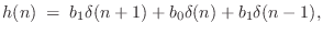
 are assumed real. The transfer function
of the general, second-order, real, zero-phase filter is
and the frequency response is
are assumed real. The transfer function
of the general, second-order, real, zero-phase filter is
and the frequency response is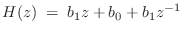 which is real for all
 .
.
- Extending the previous example, every order
 zero-phase real FIR
filter has an impulse response of the form
zero-phase real FIR
filter has an impulse response of the form
and frequency response
which is clearly real whenever the coefficients
 are real.
- There is no first-order (length 2) zero-phase filter, because,
to be even, its impulse response would have to be proportional to
 . Since the bandlimited digital
impulse signal
. Since the bandlimited digital
impulse signal  is ideally interpolated using bandlimited
interpolation [91,84], giving samples of
sinc
is ideally interpolated using bandlimited
interpolation [91,84], giving samples of
sinc --the
unit-amplitude sinc function having zero-crossings on the
integers, we see that sampling
--the
unit-amplitude sinc function having zero-crossings on the
integers, we see that sampling  on the integers yields
an IIR filter:
on the integers yields
an IIR filter:
 sinc
sinc sinc
sinc
- Similarly, there are no odd-order (even-length) zero-phase filters.
Next Section:
Odd Impulse Reponses
Previous Section:
Linear-Phase Filters (Symmetric Impulse Responses)


