


Sinusoidal Frequency Modulation (FM)
Frequency Modulation (FM) is well known as the broadcast signal format for FM radio. It is also the basis of the first commercially successful method for digital sound synthesis. Invented by John Chowning [14], it was the method used in the the highly successful Yamaha DX-7 synthesizer, and later the Yamaha OPL chip series, which was used in all ``SoundBlaster compatible'' multimedia sound cards for many years. At the time of this writing, descendants of the OPL chips remain the dominant synthesis technology for ``ring tones'' in cellular telephones.
A general formula for frequency modulation of one sinusoid by another can be written as
where the parameters
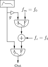
Figure 4.14 shows a unit generator patch diagram [42] for brass-like FM synthesis. For brass-like sounds, the modulation amount increases with the amplitude of the signal. In the patch, note that the amplitude envelope for the carrier oscillator is scaled and also used to control amplitude of the modulating oscillator.
It is well known that sinusoidal frequency-modulation of a sinusoid
creates sinusoidal components that are uniformly spaced in frequency
by multiples of the modulation frequency, with amplitudes given by the
Bessel functions of the first kind [14].
As a special case, frequency-modulation of a sinusoid by itself
generates a harmonic spectrum in which the ![]() th harmonic amplitude is
proportional to
th harmonic amplitude is
proportional to
![]() , where
, where ![]() is the order of the
Bessel function and
is the order of the
Bessel function and ![]() is the FM index. We will derive
this in the next section.4.9
is the FM index. We will derive
this in the next section.4.9
Bessel Functions
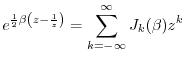
The Bessel functions of the first kind may be defined as the
coefficients
![]() in the two-sided Laurent expansion
of the so-called
generating function
[84, p. 14],4.10
in the two-sided Laurent expansion
of the so-called
generating function
[84, p. 14],4.10
where
The last expression can be interpreted as the Fourier superposition of the sinusoidal harmonics of
Note that
![]() is real when
is real when ![]() is real. This can be seen
by viewing Eq.
is real. This can be seen
by viewing Eq.![]() (4.6) as the product of the series expansion for
(4.6) as the product of the series expansion for
![]() times that for
times that for
![]() (see footnote
pertaining to Eq.
(see footnote
pertaining to Eq.![]() (4.6)).
(4.6)).
Figure 4.15 illustrates the first eleven Bessel functions of the first
kind for arguments up to ![]() . It can be seen in the figure
that when the FM index
. It can be seen in the figure
that when the FM index ![]() is zero,
is zero, ![]() and
and ![]() for
all
for
all ![]() . Since
. Since
![]() is the amplitude of the carrier
frequency, there are no side bands when
is the amplitude of the carrier
frequency, there are no side bands when ![]() . As the FM index
increases, the sidebands begin to grow while the carrier term
diminishes. This is how FM synthesis produces an expanded, brighter
bandwidth as the FM index is increased.
. As the FM index
increases, the sidebands begin to grow while the carrier term
diminishes. This is how FM synthesis produces an expanded, brighter
bandwidth as the FM index is increased.
![\includegraphics[width=\twidth]{eps/bessel}](http://www.dsprelated.com/josimages_new/mdft/img537.png)
FM Spectra
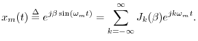
Using the expansion in Eq.![]() (4.7), it is now easy to determine
the spectrum of sinusoidal FM. Eliminating scaling and
phase offsets for simplicity in Eq.
(4.7), it is now easy to determine
the spectrum of sinusoidal FM. Eliminating scaling and
phase offsets for simplicity in Eq.![]() (4.5) yields
(4.5) yields
where we have changed the modulator amplitude
| re |
|||
| re |
|||
re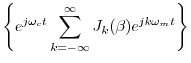 |
|||
re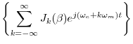 |
|||
![$\displaystyle \sum_{k=-\infty}^\infty J_k(\beta) \cos[(\omega_c+k\omega_m) t]$](http://www.dsprelated.com/josimages_new/mdft/img545.png) |
(4.9) |
where we used the fact that
Next Section:
Analytic Signals and Hilbert Transform Filters
Previous Section:
Sinusoidal Amplitude Modulation (AM)


