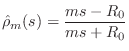
In the case of a mass  , we have
which implies its
reflectance is, from Eq.

(
F.13),
Setting

gives
and this choice also turns out to eliminate the delay-free path
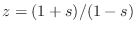
in the digital version. In view of the expression for the
inverse
bilinear transform in Eq.
(
F.12),
i.e.,
, the
bilinear transform of

is immediately seen to be
where we defined
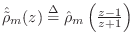
.
The corresponding
difference equation for the
wave digital mass is
and its wave flow diagram is drawn in Fig.
F.2.
Figure F.2:
Wave flow diagram for the wave digital
mass. Note that the wave variables are written in the time domain as
is customary in digital filter diagrams, while it would be more
consistent (with the  block) to keep them in the frequency domain
as
block) to keep them in the frequency domain
as  and
and  .
.
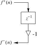 |
Thus, the wave digital mass is simply a unit-sample delay and a
negation. The fact that the value of the mass has been canceled out
will be addressed below in the subsection on ``adaptors,'' i.e., it
only affects interconnection with other elements. For now, just
remember that the reference impedance was chosen to be equal to the
mass in order to get this simple wave flow diagram. Also note that
the WDF mass simulator has no delay-free path from input to output.
Next Section: Wave Digital SpringPrevious Section: Summary of Wave Digital Elements