


The correct answer to the quiz of @apolin
The correct answer to the @apolin quiz can be easily explained using the following Simulink model:
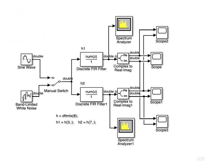
In MATLAB you have to initialize the two filters:
h = dftmtx (8);
h1 = h (3, :); % The filter of the quiz
h2 = h (7, :); % The mirrored filter
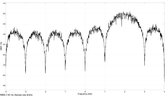
The impulse responses of the filters h1, h2 are complex and the responses to a broadband random signal are also complex. The two spectrum analyzer blocks then show the PSD, typical for analytical signals:
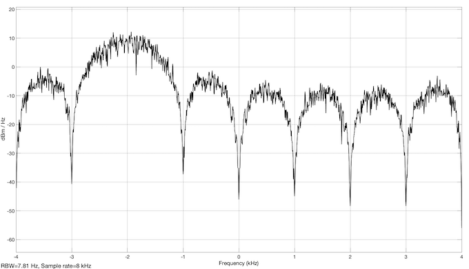
The third line of the dftmtx (8) as the impulse response of the filter represents a bandpass filter with center frequency - 2 kHz. Students without experience in this field do not understand what a signal with - 2 kHz can look like. Because sin (-phi) = sin (phi + pi) you can always convert a vibration with a negative frequency into a vibration with a positive frequency.
The model can be excited with a signal of frequency 2 kHz and phase zero or 2 kHz and phase pi. The signals remain the same. The real parts are the same and in phase for the two filters and the imaginary parts are the same and in opposite phase. If you use a frequency of 6 kHz (Fs - 2000 = 8000 - 2000 = 6000 Hz) instead of 2 kHz for the signal, the representations do not change either. The 6 kHz frequency signal, that the sampling theorem does not meet, is aliased to a 2 kHz frequency signal and opposite phase.
You can examine these facts on the model and I hope you enjoy experimenting.
- Comments
- Write a Comment Select to add a comment
To post reply to a comment, click on the 'reply' button attached to each comment. To post a new comment (not a reply to a comment) check out the 'Write a Comment' tab at the top of the comments.
Please login (on the right) if you already have an account on this platform.
Otherwise, please use this form to register (free) an join one of the largest online community for Electrical/Embedded/DSP/FPGA/ML engineers:


