


Implementing Impractical Digital Filters
This blog discusses a problematic situation that can arise when we try to implement certain digital filters. Occasionally in the literature of DSP we encounter impractical digital IIR filter block diagrams, and by impractical I mean block diagrams that cannot be implemented. This blog gives examples of impractical digital IIR filters and what can be done to make them practical.
Implementing an Impractical Filter: Example 1
Reference [1] presented the digital IIR bandpass filter shown in Figure 1(a) where HNO(z) is a FIR notch filter and variable K is a constant.
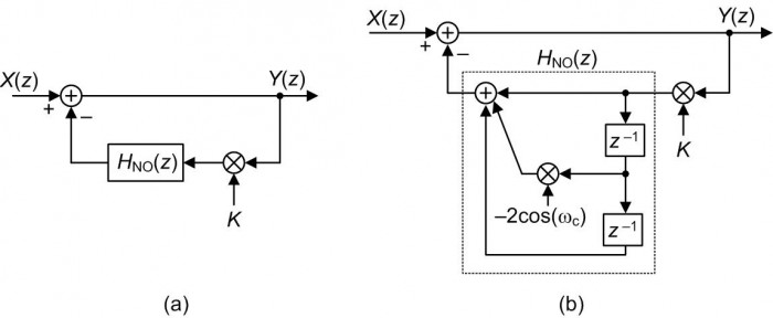
Figure 1: Reference [1]'s proposed IIR bandpass filter: (a) high-level depiction; (b) detailed signal path depiction.
The idea behind this bandpass filter is to subtract the output of the notch filter from the X(z) input to produce a narrow bandpass filter output. The Figure 1(a) filter's z-domain transfer function is:
$$H_{\mathsf{BP}}(z) = \frac{Y(z)}{X(z)} = \frac{1}{1 + KH_{\mathsf{NO}}(z)}\tag{1}$$
where the bandpass filter's HNO(z) term is a 2nd-order FIR notch filter defined by$$H_{\mathsf{NO}}(z) = 1-2\mathsf{cos}(\omega_c)z^{-1}+z^{-2}.\tag{2}$$
In Eq. (2) variable $\omega_c$, where $0<{\omega_c}<\pi$, represents the center-frequency of the FIR filter's notch measured in radians/sample.
Based on Eq. (2) the proposed bandpass filter can be depicted as shown in Figure 1(b). The Figure 1 filter seems like a plausible design but is in fact impossible to implement (i.e., it's impractical). Here's why.
The Problem
The trouble with the above bandpass filter is that it contains a feedback signal path containing no delay element (a delay-less signal path) as shown by the bold arrows in Figure 2.
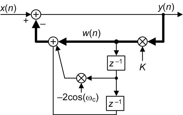
Figure 2: Time-domain depiction of the impractical bandpass filter with the delay-less signal path highlighted in bold.
Upon the arrival of an x(n) input sample, in order to compute a y(n) output sample we first need to compute the w(n) feedback sample. But to compute w(n) we need y(n)! That delay-less signal path means the Figure 2 filter cannot be implemented.
The Solution: Algebra to the Rescue
As it turns out, algebraic expansion of the HBP(z) equation produces a new filter z-domain transfer function that can be implemented. As shown in Appendix A, we can plug Eq. (2) into Eq. (1) to obtain a practical transfer function of:
$$H_{\mathsf{BP,Practical}}(z) = \frac{\alpha}{1+2K{\alpha}\mathsf{cos}(\omega_c)z^{-1}+K{\alpha}z^{-2}}\tag{3}$$
where ${\alpha}=1/(1+K)$, and $K≠-1$. Unlike the Figure 2 filter, the Eq. (3) bandpass filter can be implemented with no problem as shown in Figure 3.
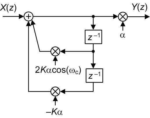
Figure 3: Practical (implementable) version of the impractical Figure 1 bandpass filter.
Implementing an Impractical Filter: Example 2
A second example of an impractical filter, proposed in Reference [2], is the narrowband digital notch filter shown in Figure 4.
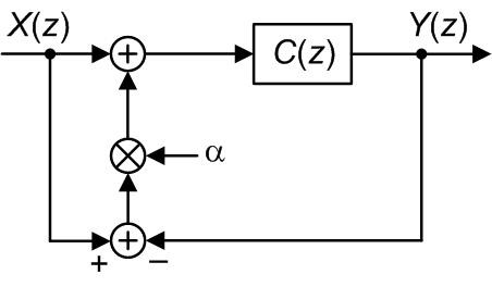
Figure 4: High-level depiction of Reference [2]'s proposed IIR notch filter.
where C(z) is a notch filter and variable a is a constant. The z-domain transfer function for the proposed Figure 4 IIR filter, derived in Appendix B, is:
$$H_\mathsf{N}(z) = \frac{Y(z)}{X(z)} = \frac{(1+\alpha)C(z)}{1+{\alpha}C(z)}.\tag{4}$$
The C(z) function is a traditional 2nd-order narrowband IIR notch filter whose transfer function is:$$C(z) = \frac{1-2\mathsf{cos}(\omega_c)z^{-1}+z^{-2}}{1-2\rho\mathsf{cos}(\omega_c)z^{-1}+\rho^2z^{-2}}\tag{5}$$
where variable $\omega_c$, $0<{\omega_c}<\pi$, is the center-frequency of the filter's notch measured in radians/sample, and $\rho$ is the radii of the conjugate poles' z-plane locations. Based on Eq. (5) the proposed notch filter can be depicted in more detail as shown in Figure 5.
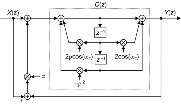
Figure 5: Detailed signal path depiction of the HN(z) notch filter.
The Figure 5 bandpass filter contains a delay-less feedback signal path as shown by the bold arrows in Figure 6.
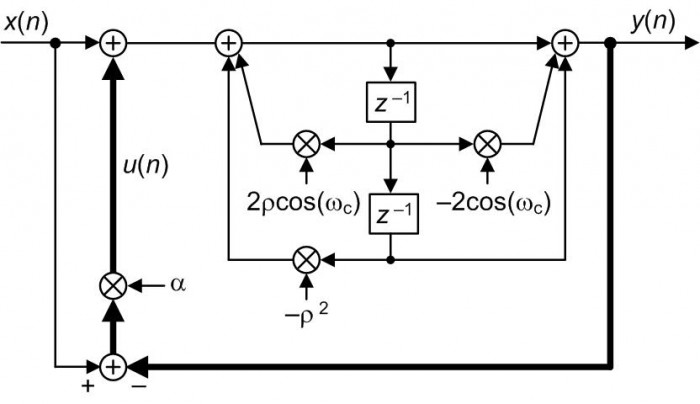
Figure 6: Time-domain depiction of the impractical HN(z) notch filter with the delay-less signal path highlighted in bold.
That delay-less signal path makes the Figure 6 filter impractical because to compute a y(n) output sample we first need to compute the u(n) feedback sample. But to compute u(n) we need y(n). Similar to the Figure 2 filter, the Figure 6 filter cannot be implemented.
Again, as we did in Example 1, algebraic expansion of the HN(z) equation produces a new filter z-domain transfer function that can be implemented. Substituting Eq. (5)'s C(z) expression into Eq. (4), as shown in Appendix C, we produce a practical transfer function of:
$$H_{\mathsf{N,Practical}}(z) = \frac{1-2\mathsf{cos}(\omega_c)z^{-1}+z^{-2}}{1-2\frac{\rho+\alpha}{1+\alpha}\mathsf{cos}(\omega_c)z^{-1}+\frac{\rho^2+\alpha}{1+\alpha}z^{-2}}\tag{6}$$
where ${\alpha} ≠ -1$. This new HN,Practical(z) function is a traditional 2nd-order IIR filter that can be implemented using the block diagram shown in Figure 7.
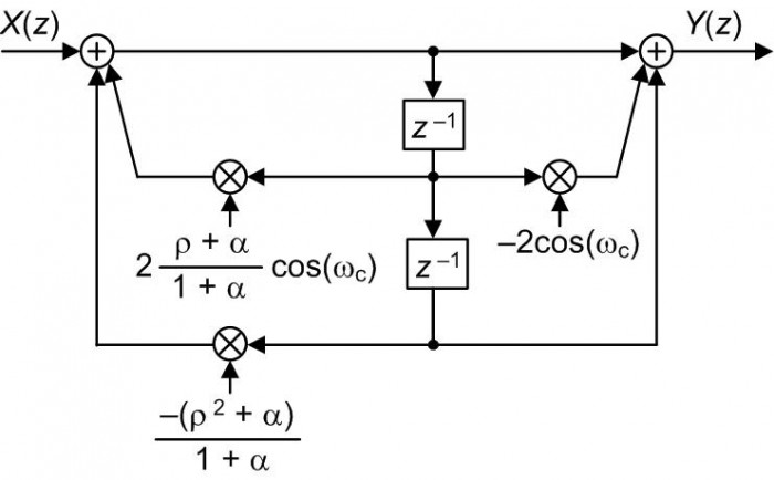
Figure 7: Practical (implementable) version of the impractical Figure 4 notch filter.
Conclusion
The bottom line of this blog is: When you encounter a digital network's block diagram that is impractical (i.e., impossible to implement because it contains a delay-less feedback signal path), algebraic analysis of the network's z-domain transfer function may well lead to a new and equivalent block diagram that is possible to implement.

Postscript: December, 2017
In my original July 2016 version of this blog I presented the following Figure 8 network and claimed it to be impractical.
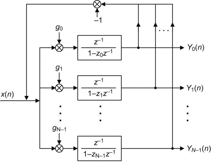
Figure 8: Reference [3]'s spectrum analysis network.
But, as was pointed out to me by Prof. Zsolt Kollár (Budapest University of Technology and Economics, Hungary) I was mistaken. If we draw the details of the resonators in Figure 8 we have Figure 9, and that network can indeed be implemented due to the delay elements in each path.
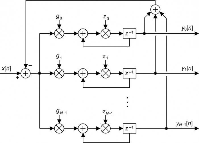
Figure 9: Expanded version of the Figure 8 network.
Upon arrival of an x[n] input sample we compute all the outputs of the zk multipliers, shift those products through their delay elements, and wait for the next x[n+1] input sample. No problem. As the cowboys in Texas would say, "The Figure 8 system works real fine."
References
[1] S.Engelberg, “Precise Variable-Q Filter Design,” IEEE Signal Processing Magazine, Sept. 2008, pp. 113–119.
[2] S. Pei, B, Guo, and W. Lu, "Narrowband Notch Filter Using Feedback Structure", IEEE Signal Processing Magazine, May 2016, pp. 115-118.
[3] G. Peceli, G. Simon, "Generalization of the Frequency Sampling Method", IEEE Instr. and Meas. Conference, Brussels Belgium, June 1996.
https://www.researchgate.net/publication/3632671_Generalization_of_the_frequency_sampling_method
Appendix A: Derivation of Eq. (3)
We derive Eq. (3) by starting with the above Eq. (1), repeated here as:
$$H_{\mathsf{BP}}(z) = \frac{1}{1 + KH_{\mathsf{NO}}(z)}.\tag{A-1}$$
Substituting the notch filter's HNO(z) from Eq. (2) into Eq. (A-1) yields:
$$H_{\mathsf{BP}}(z) = \frac{1}{1 + K[1-2\mathsf{cos}(\omega_c)z^{-1}+z^{-2}]}$$
$$= \frac{1}{(1 + K)-2K\mathsf{cos}(\omega_c)z^{-1}+Kz^{-2}}.\tag{A-2}$$
Next, dividing Eq. (A-2)'s numerator and denominator by (1+K) we produce the desired expression for the Figure 1 proposed bandpass filter's equivalent and practical transfer function of:
$$H_{\mathsf{BP,Practical}}(z) = \frac{\alpha}{1+2K{\alpha}\mathsf{cos}(\omega_c)z^{-1}+K{\alpha}z^{-2}}\tag{A-3}$$
where ${\alpha}$ = 1/(1+K), and K ≠ -1.
Appendix B: Derivation of Eq. (4)
The following derivation was graciously supplied to me by Reference [2]'s co-author Bo-Yi Guo. Master's student Guo derived Eq. (4) by redrawing Figure 4 as shown in Figure B1.
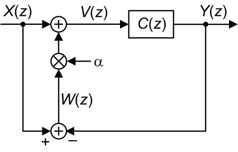
Figure B1: Reference [2]'s proposed IIR notch filter.
From Figure B1, we start with
$$W(z) = X(z)-Y(z)\tag{B-1}$$
and
$$V(z) = X(z)+{\alpha}W(z).\tag{B-2}$$
Replacing W(z) in Eq. (B-2) with Eq. (B-1), we have:
$$V(z) = X(z) +{\alpha}(X(z)–Y(z)).\tag{B-3}$$
The Y(z) output can be expressed as:
$$Y(z) = V(z)C(z).\tag{B-4}$$
Replacing V(z) in Eq. (B-4) with Eq. (B-3) gives:
$$Y(z) = [X(z) + {\alpha}(X(z)–Y(z))]C(z)$$
$$= (1+{\alpha})X(z)C(z)-{\alpha}Y(z)C(z).\tag{B-5}$$
Rearranging Eq. (B-5) yields our desired HN(z) transfer function as:
$$H_\mathsf{N}(z) = \frac{Y(z)}{X(z)} = \frac{(1+\alpha)C(z)}{1+{\alpha}C(z)}.\tag{B-6}$$
Appendix C: Derivation of Eq. (6)
We derive Eq. (6) by starting with the above Eq. (4) repeated here as:
$$H_\mathsf{N}(z) = \frac{(1+\alpha)C(z)}{1+{\alpha}C(z)}\tag{C-1}$$
or after dividing through by C(z),
$$H_\mathsf{N}(z) = \frac{1+\alpha}{\frac{1}{C(z)}+\alpha},\tag{C-2}$$
recalling from Eq. (5) that
$$H_{\mathsf{N,Practical}}(z) = \frac{1-2\mathsf{cos}(\omega_c)z^{-1}+z^{-2}}{1-2\rho\mathsf{cos}(\omega_c)z^{-1}+\rho^2z^{-2}}.\tag{C-3}$$
Next we rewrite Eq. (C-2) by separating C(z) into its numerator and denominator parts as:
$$H_\mathsf{N}(z) = \frac{1+\alpha}{\frac{1}{C_\mathsf{numer}(z)/C_\mathsf{denom}(z)}+\alpha}= \frac{1+\alpha}{\frac{C_\mathsf{denom}(z)}{C_\mathsf{numer}(z)}+\alpha}$$
$$= \frac{(1+\alpha)C_\mathsf{numer}(z)}{C_\mathsf{denom}(z)+{\alpha}C_\mathsf{numer}(z)}.\tag{C-4}$$
Substituting Eq. (C-3)'s numerator and denominator terms into Eq. (C-4) we have:
$$H_{\mathsf{N}}(z) = \frac{(1+\alpha)[1-2\mathsf{cos}(\omega_c)z^{-1}+z^{-2}]}{1-2\rho\mathsf{cos}(\omega_c)z^{-1}+\rho^2z^{-2}+\alpha[1-2\mathsf{cos}(\omega_c)z^{-1}+z^{-2}]}$$
$$= \frac{(1+\alpha)[1-2\mathsf{cos}(\omega_c)z^{-1}+z^{-2}]}{(1+\alpha)-2(\rho+\alpha)\mathsf{cos}(\omega_c)z^{-1}+(\rho^2+\alpha)z^{-2}}\tag{C-5}$$
which is Reference [2]'s Eq. (15). Finally, dividing Eq. (C-5)'s numerator and denominator by (1+$\alpha$) we produce the desired equivalent and practical expression for the proposed notch filter's transfer function of:
$$H_{\mathsf{N,Practical}}(z) = \frac{1-2\mathsf{cos}(\omega_c)z^{-1}+z^{-2}}{1-2\frac{\rho+\alpha}{1+\alpha}\mathsf{cos}(\omega_c)z^{-1}+\frac{\rho^2+\alpha}{1+\alpha}z^{-2}}\tag{C-6}$$
where ${\alpha} ≠ -1$.
- Comments
- Write a Comment Select to add a comment

Thank you for your kind words.
To post reply to a comment, click on the 'reply' button attached to each comment. To post a new comment (not a reply to a comment) check out the 'Write a Comment' tab at the top of the comments.
Please login (on the right) if you already have an account on this platform.
Otherwise, please use this form to register (free) an join one of the largest online community for Electrical/Embedded/DSP/FPGA/ML engineers:


