Digital Filters that have prescribed phase shift
 Started by 4 years ago●14 replies●latest reply 4 years ago●825 views
Almost sixty years ago I needed an all-pass recursive digital filter with two outputs, such that the phase difference between the outputs was a very good approximation to 90 degrees, over a specified band. There was a technique for designing such filters as analog filters, which I found in the book "Passive Network Synthesis", J. E. Storer, McGraw Hill, 1957. I translated the analog design technique to one for digital filters using the bi-linear transform. I might have been the first person to ever do that for a 90 degree phase splitter.
Storer's book says that the same design technique can produce phase differences of any amount, but it was either too hard to understand, or perhaps contained errors. Clearly the 90 degree case is useful because there are many applications, either for the phase splitter or for a 90 degree phase shifter, which is a single filter whose output is a 90 degree shift of the input. The latter filter would be unstable by normal means but today it is quite practical and has seen some use in single sideband systems, such as radar, sonar, some modems, etc.
This spring, under enforced isolation, I went back to Storer's book chapter to try to generalize the phase shift network to an arbitrary phase shift P over a designated band ta < f < tb with a specified maximum error tolerance e. The network uses N multiplications per sample and I find the least possible N, and the N poles and N zeroes. Because the network is allpass, the poles and zeroes are reciprocals, and they are all real.
I would still need a lot of work to make the technique mathematically rigorous, but I have tried it on enough examples that I am confident that it works.
But I don't know of any applications where it might be useful. So here's the question: Can anybody think of a realistic requirement for such a network?
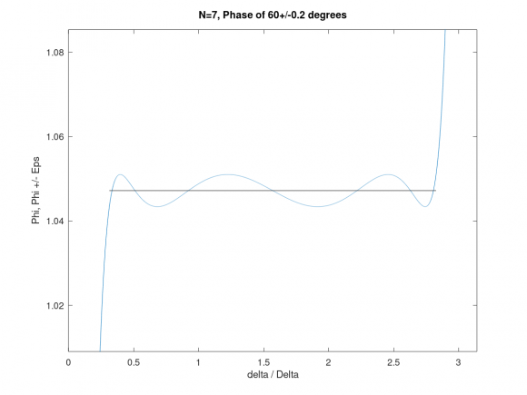
The attached file is an example of a phase shifter for 60 +/- 0.2 degrees between pi/10 and 9 pi/10. It needs N=7 multiplications per sample.
Sorry, I don't seem to know how to attach a file.

It's common to use a pair of allpass IIR filters with +/-45deg shifts as an analytic signal converter (aka Hilbert transform) that can generate a complex (quadrature) signal from a real signal. This is frequently used for doing frequency shifts of audio signals for electronic music or feedback suppression in PA systems.
Thanks emeb. Is it common knowledge how to design such filters? I am using a mapping based on Jacobian elliptic functions and the resulting designs are provably optimum in the sense that they use the least order N for a given tolerance.
Before posting the question, I looked on the web for whatever I could find about designing constant phase approximations and I couldn't find anything. Can you point me to a reference?
Also, if you want a given sequence and its Hilbert transform, there's a technique for using the 90 degree phase shifter that saves a lot of work. For the 90 degree case, which is widely used, make N odd and make the passband symmetric about 90 degrees. You then save arithmetic in two separate ways. First, the transfer function turns out to be a function of z^2 which means that you have (N-1)/2 multiplications per sample for an N pole filter. Second, you really need to compute only odd numbered samples because the single sideband signal i[n]+jq[n] has half the bandwidth of the original, so it can be 2:1 downsampled - and why compute samples that you are going to throw away?
There is a pretty good write-up here about the two path allpass Hilbert transform.
gretzteam, I haven't seen it before, but it gives a specific case, which I would call N=9. It's a 90 degree case. There's a set of formulas for the 90 degree case so no successive optimization software is necessary. The formulas involve elliptic integrals of the first kind. You can compute an elliptic integral of the first kind using MATLAB's built-in function "ellipke". The formulas you need are in Storer's book. Here's a short snippet of MATLAB code for finding N given the band edges ta, tb and the tolerance epsi.
k = tan(ta/2)/tan(tb/2);
kp = sqrt(1-k^2);
k1 = ( (1-tan(epsi/2))/(1+tan(epsi/2) ) )^2 ;
[Kofk,E] = ellipke(k^2);
[Kofk1,E] = ellipke(k1^2);
[Kpofk,E] = ellipke(1-k^2);
[Kpofk1,E] = ellipke(1-k1^2);
N = Kpofk*Kofk1/(Kpofk1*Kofk);
N= ceil(N); % filter order
My 1969 book Gold and Rader, Digital Processing of Signals spells out the design procedure for the 90 degree case on pages 90-93. This was before there was MATLAB and the elliptic integrals and Jacobian elliptic functions in that design procedure were to be computed by convergent series, a mathematical nightmare. It turns out that there are much better ways to compute elliptic functions lightningly fast and MATLAB has them built in.
The case in http://yehar.com/blog/?p=368 gets 4 multiplications per sample with N=9 by using the trick I mentioned in my reply to emeb. In fact, the trick is patented (US patent 4794556) although the patent has long since expired.
I don't have a design equation for the non-90 degree case. Storer gives one on page 301, Eqs(30.30a,b) but, as I have said, it is either wrong or I can't understand it. One thing that I have noticed is that if you use the well known formula for the 90 degree case relating N and epsi you get a better epsi for the same N when you are trying to get a different nominal phase other than 90 degrees. The improvement in epsi for N fixed, when you vary the desired phase, is almost perfectly linear. But I don't have a formula for epsi vs N. In practice it doesn't matter much. N is not going to be more than, say, 10, so you can start with a small integer N, see what epsi you get, and if necessary try the next larger N.
As I write this I wonder if I should go back to Storer's book and try again to understand it.
I haven't designed 2-arm IIR filter style Hilbert transforms from first principles myself - I assume most folks looking for such would likely begin with common filter design algorithms and then apply optimization processes to tweak them up. If you've got a design process that allows you to specify phase shift, frequency range, filter order, etc that would be a handy thing to have.
Your insight regarding bandwidths sounds correct. I have built FIR style Hilbert transforms by starting with a half-band filter and parsing it out into a pure N/2 delay and a (N+1)/2 delay, then applying an Fs/4 modulation to align the DC point. This type of analytic signal conversion works well for high sample-rate system.
The 90 degree FIR half-band filter, zeroes rotated by ninety degrees, gives you an FIR Hilbert transformer approximation, phase a perfect 90 degrees, but it is not all-pass. But if you design a recursive half-band filter using elliptic functions, you can rotate its poles and zeroes by 90 degrees. That gets you the exact same poles and zeroes that you get from the technique I have used for the phase-splitter.
I'm trying to think more about your suggestion of a 45 degree filter and a -45 degree filter. I'm pretty sure that if I had the poles and zeroes of a 45 degree filter, I could use some sort of symmetry principle to get the poles and zeroes of a -45 degree filter. One filter would be the inverse of the other, so we should be able to just swap the poles and zeroes of one for the zeroes and poles of the other. On the other hand, using the 45 degree filter in cascade with itself would give a 90 degree filter but it is probably not optimum because each constant multiplier is used twice per sample. I would need to think that out more carefully, though.
Actually if you design a filter with 45 degree phase shift ,say with 65 coefficients, to get -45 degrees just use the coefficients backwards.
Sorry, I don't seem to know how to attach a file.
Use  for file upload operation.
I did try that. It let me choose a file, which I did. But apparently there is some other step because the file I chose didn't seem to show up. Using drop and drag, nothing happens. Using Browse I find my file and the name of the file shows up to the right of the Browse box, but then nothing happens.
Usually there are only certain type files allowed to upload.
Which type your file is (ascii, binary).
It's a pdf file. It's a plot made by GNU octave, which is a MATLAB equivalent system that's free.
On Octave, save as an image file (.png seems to work) and upload with feature...
Thanks, that seems to work.