


High Frequency Linear Array BeamForming
Hi all
I am doing some research on High Frequency Linear Array beam forming (for imaging sonar).For that purpose, a linear Rx Array of 100 channels have been constructed with inter channel spacing of 14.3mm. A transmitting Tx probe operating at 420 KHz (approx. 300 cycles pulse) is placed at distance of approx. 8.9m from Rx array in water tank of dimensions (Length=12m, Width=8m, Depth=8m). The depth of Tx probe and Rx array is around 4m. The array data has been simultaneously acquired at sampling rate of 2Msamples/s/channel using NI ADC cards. The ADC cards and pulse generator for Tx probe are accordingly synchronized. The acquired digitized data is attached in this post as array_data_MATLAB.zip. There is 'sensor_matrix.mat' file in it containing 65536 samples each of 100 channels of Rx array.
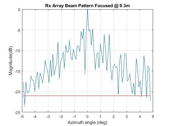
I have done some array beam forming on it along with focusing (at 9.3m approx.) and beam pattern result is drastic (far worse than simulated one) and shown below. The useful sector is around 10 degree and MATLAB 'chebwin' shading with -21dB side lobes has been used.
If someone has done such work, can he/she kindly beam form this data ('sensor_matrix.mat') and share beam pattern results with me? I want to know in steps where is issue?, in my processing, in setup or in both?
Thanks & Regards
Nauman
Hi Nauman,
I have worked on microphone array beamforming so thought to give this question a try. I do not fully understand the question though. The depth of water tank is 8m and yet you have focused the array at 9.3m and depth of Rx and Tx to be 4m. Am I missing something here? Did you use delay and sum beamforming algorithm? Also, I do not see any files attached.
With speed of sound in water of 1480 m/s and Tx frequency of 420KHz, the wavelength comes out to be 3.52 mm, much smaller than Rx inter-channel spacing of 14.3 mm. This would result in spatial aliasing which could be the side lobes apparent in your data. Please let me know your thoughts.
Regards,
Sagar
Hi Sagar
1.As Length of water Tank is 12m, Rx array and Tx probe are placed apart around 8.9m lengthwise. As depth of Tank is 8m, both Rx array and Tx probe are immersed in middle of water column i.e. around 4m. Ideally, as Tx Probe is 8.9m apart from Rx array, Rx array focus should be at 8.9m but i am getting better results when focusing is being done at 9.3m (Remember, this focusing is being done in software in receive processing).
2.I am use delay and sum beamforming using 2D FFT method. I have also tried Phase Shift beam former but same results are achieved.
3.Sorry for that. I tried many times using 'insert File' but was not able to upload .zip file. Does this forum allow upload of zip files?
4.I have simulated grating lobes (spatial aliasing), they are formed outside +/-7 degree region. I am using only +/-5 deg sector as shown in graph.
Thanks & Regards
Nauman


