


Do we have to insert the DC null in OFDM when using RF direct sampling ADC architecture?
 Started by 4 years ago●17 replies●latest reply 3 years ago●892 views
Generally, DC Nulls are added in OFDM because zero-IF receivers don't pass the DC component. But what if I use an RF direct sampling architecture? Will there be DC offset? If not, then is it okay not to insert a DC null?
Thank you in advance!

In the cases where the DC subcarrier is left vacant it was usually so that an analog direct-conversion mixer could be used. It usually wasn't possible to completely eliminate a DC component coming out of one of those due to bleed-through of the LO, so the DC carrier would be corrupted by however much of the LO got through the mixer.
With direct or IF sampling and a digital mix to baseband, there is no LO bleed-through, so the DC carrier is usable.
It's often just whatever technology was in use or expected to be used when the standard was written.

I am a bit lost here. For ofdm we always expect some analogue mixing as the digital mixing is usually lower down. So what am I missing here. I know 4G/5G uplink (from mobile to radio) uses the dc bin though downlink 4G does not and I assume it is to do with symmetry achievement of even number of subcarriers. So how come these systems don't care about analogue mixer bleeding.
The only mix that will put the LO energy at the DC subcarrier is a direct-conversion complex mix to baseband, since the LO is exactly at the center carrier frequency. Any real-valued heterodyne or super-heterodyne mix does not do this, since the LO frequency is not in-band with the signal. Many standards, e.g., IEEE 802.11, were developed assuming that implementers would want to use analog direct-conversion, since it provides a wide tuning range with only one mixing stage. Even with a heterodyne RF mix, if the final or IF mix is complex it is susceptible to carrier bleed-through at DC.
In single-carrier systems this has to be adjusted out or compensated, but in OFDM you can elect to just not populate the DC subcarrier. This lets you bypass bench adjustment or use a lower-cost mixer, etc., etc.
Since RF or IF data conversion has gotten more practical at higher frequencies, or the RF architectures have gotten cheaper/better to allow it, the digital downconversion eliminates or reduces the LO bleed-through sufficiently that it just isn't a problem.
It's a decision made during the standard development whether or not to populate the DC subcarrier, based on assumptions about whether it will be an issue for implementation or not. If everybody votes to populate the DC subcarrier, it goes in. ;)
Thank you very much for the detailed reply. Actually I am a Masters student and I am writing my thesis which is to implement an all-digital frequency-hopped OFDM system using RF sampling data converters. I wanted to ask this question so that I can write in my thesis that adding a DC null is optional. I actually found one reference in Xilinx's RF data converter user guide. There it is mentioned that the DC offset problem can be mitigated. However, some other documents of TI RF sampling ADCs mention some techniques to get rid of this problem to an extent.
Very cool. I'm glad you're getting it sorted out.
The same problems exist for single-carrier signals, where the resulting DC offset in a constellation must be removed for reliable detection of the symbols. In those systems DC offset loops in the I and Q channels remove the DC in typical receivers. Even in bursty systems this can be done between received bursts as long as the LO is present.
For a frequency hopping system the DC offset may be frequency dependent and might have to be solved for each hop if the LO is used to steer the hops. I've not personally tried this, though.
the self mixing properties of the ADC of the analog mixers down converts a DC line on both I and Q... the truncation transfer function of the ADC always injects half an LSB of DC to both I and Q..... the truncation arithmetic (scaling and lower order bit discarding of products) in the FFT injects a negative half an LSB to both I and Q. In the days of IS-95, spread spectrum, the correlators spread the dc out of the way while despreading the signal... There is no rescue of the DC term bias in the DC bin.... I tell my students we donate the DC bin to the DSP gods to keep the volcano from erupting.
Actually the near empty DC bin is useful when there is a large frequency offset... we would violate the Nyquist criterion due to a large change in angle per short preamble interval and would apply an incorrect de-spin operator to bin center the offset signal... we would search in the neighborhood of bin "0" to find that "empty" bin and offset the bin assignment to recover from the incorrect frequency translation... if the spinning rate is 1 degree per sample for 32 samples of short preamble we would see the 32 degrees phas term in the cross correlator, divide out the 32, and correct the 1 degree per sample offset.. on the other hand if the spin rate is 10 degree per sample we would see 320 degree as -40 degree... and divide out the 32 to have a correction term of-1.25 degree per sample... that correction would bin center all the bins with a bin offset... check if bin is empty would let us know about the offset... and locating the -1 bin offset would be our recovery from the offset.
fred h
Current digital computations such as fft and any truncation can avoid dc by using dc unbiased rounding.
As to ADC I can assume that a good quality ADC will manage sampling with basic rounding of midpoints towards the correct step in the digital ladder. I expect they do not (and need not) do dc unbiased rounding as presence of random noise eliminates the need for that. Compared to the analogue mixer bleed through, any other digital dc bias is trivial.
the adc always estimates the signal from below... the highest discrete level not higher than the measured signal... it performs truncation....successive approximation discards a state above the hold sample... a flash converter does the same thing.... comparators can be auto calibrated to avoid analog offsets... but the decision process never outputs samples values above the hold value.... the dither reduces the quantization error but not the DC bias error.
The arithmetic also induces the same bias... discarding a lower order bit when the amplitude is positive reduces the size of the number, 1 bit half the time for an average offset of -1/2 bit. Discarding a lower order bit when the number is negative moves the number closer to the reference, which for a negative number is the most negative number... thus the number becomes a larger negative number, by 1/2 a bit... Rounding helps but takes extra clock cycles.. and the truncation occurs when scaling sums to avoid overflow and also occurs when a product forms a double precision product and is returned to single precision. There are .some signals contain DC and a dc-canceler would do dame to the DC content. In high end audio processing, the scale bits are not discarded but are rather returned to the next sample by a sigma-delta loop... audio does not contain DC and is often transformer coupled to the ADC.
fred h
Hi Fred,
Do you imply that ADC error is one lsb max. My understanding it is 1/2 lsb max error and that is the basis of SNRQ formula. Please see attached extract from a reputable source. As such the error is equivalent to basic digital rounding which we do regularly. There is no dc offset except for exact mid points which naturally are as far from top step as from bottom step.
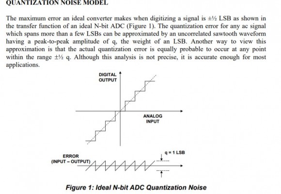
the ramp is the input-output relationship without quantizing.... the staircase is the instantaneous non linearity of a rounding quantizer... rela quantizers don't round, the truncate so the staircase drops half a quantile (step amplitude) and the error triangles, similarly drop half a quantile with a DC average -q/2. If you have a copy of the sklar book on digital communications see chapter on source coding (mine)... also look at my ppt on the sources of DC in receiver
Thanks Fred,
Based on that I assume all ADCs are not rounding quantisers but truncating quantisers. Yet the SNR of quantisation noise assumes half bit error (i.e. rounding) so the 6dB per bit SNR is not really correct as the error doubles from lsb/2 to one lsb plus dc offset. Any idea what is going wrong here?
Kaz

The formula SNR = 6 dB/bit + 1.76 dB is insensitive to DC offsets. This result comes from the variance of a uniform distribution as being q/12. If you apply that distribution to extend from 0 to q, or -q/2 to +q/2 you will end up with the same variance (noise estimate). DC offsets are not typically included in noise estimates (we subtract the mean when determining variance and standard deviation), so it doesn't effect that formula. So whether we round or truncate the variance of the quantization noise is not changed but a DC offset is introduced.
Hi DanBoschen,
Thanks for correcting my thoughts that mixed up dc bias and error probability.
In return I will add that the rule of 6.02N + 1.76 dB can be extended to any signal, any power level as follows:
SNRQ = 6.02*N + 4.77 + dBFs
where dBFs = 20*log10 (rms/Full scale)
The single tone full scale case then becomes:
6.02*N + 4.77 +20*log10(.707/1)
= 6.02*N + 1.76dB
I got that from some old paper which showed its derivation, and it could be helpful to calculate this type of noise instead of using spectrum noise floor.Thanks, that is handy! The derivation now that I think about it seems straightforward. What we see is we are just lowering "S" in SNR directly: SNR = 20Log(Sine Wave rms)/(qNoise rms) - (Signal rms/ Sine Wave rms), which implies the total quantization noise power doesn't change as the signal power is varied.
That makes sense from my own experience; the quantization noise is reasonably estimated as a uniformly distributed white noise process with same variance (q/12) even if we change the power level of an arbitrary input signal AS LONG AS that input is (1) independent of the sampling clock, (2) traverses at least a few quantization levels from sample to sample, and (3) is within the "usable" dynamic range of the ADC (i.e., not clipping and the 2nd req't we already mentioned).
The 6.02*N+1.76 dB which is for the case of a full scale sine wave specifically is just a point of reference for full scale ultimately referred back to the receiver input (knowing that the peak to average of the sine wave which is -3 dB), from which we establish where the quantization noise floor is (and add as an independent noise to all the other "noise figure" sources we also reference back to the receiver input). That floor as a magnitude quantity in standard deviation will stay the same as we vary the standard deviation of an arbitrary input. Therefore if we're content with the derivation of 6.02dB+1.76dB for a sine wave (which is straight forward from the q/12 variance relative to the Vpp/8 variance for the sine wave) we can extend that to your formula as the standard deviation of the waveform compared to the standard deviation of the sine wave (using 4.77 dB) or the standard deviation of the waveform directly referenced to full scale of the sine wave (using 1.76 dB).
What we must be clear about however is "Full scale" as used above is still the "Full scale" for a sine wave specifically and not what we may decide is full scale for an arbitrary waveform which may be difficult to resolve.
Wow! Thank you very much for such a detailed reply. I am beholden!

I can tell you that Docsis 3.1 OFDMA uses direct D/A to RF and direct A/D from RF. All the bins in the frame are filled including the "DC" term.
Hope that helps,
Mark Napier
4G Downlink ofdm keeps dc bin empty.
5G fills it.
so it is optional


