


correlation of two complex signals
 Started by 2 years ago●19 replies●latest reply 2 years ago●953 views
I have two complex signals (each a frequency sweep). I need to check delay/advance between them.
The first signal is a reference I generate in Matlab. The second signal is captured in our hardware setup.
When I correlate the complex pair (in Matlab) it is hardly useful as the peak is noisy and not obvious.
When I correlate real parts only or imaginary parts only I get clean same peaks in either case.
When I correlate amplitudes I get a clean triangle but the peak is different, possibly wrong as I can check plots by eye.
My conclusion is that I better use real or imaginary parts, but not amplitude and not complex pair.
This does not apply to auto-correlation as I get the same peak locations always.
Any thoughts please.
What could be the cause? IQ imbalance?
Thanks Kaz

Something is not being done correctly. The magnitude of the output of the correlation function should have a strong peak if the functions are correlated. If it doesn't, there's an error somewhere.
As mentioned, one of the vectors should be conjugated before doing the correlation.
You can always check any functions being used by coding a loop to do the complex multiplies and accumulation and comparing results.
Hi Slartibartfast,
That's what I expect but I am not getting it.
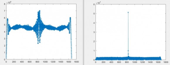
here are two plots:
left is complex vs complex using matlab xcorr
right is real vs real using matlab xcorr, this same behavior happens with imaginary versus imaginary or real versus imaginary. or if use complex but re-conjugate one member.
after several attempts it turned out to work if I generate the Zaddoff Chu frequency sweep as conjugate of what I assumed:
The equation I got from search originally is this:
zd = exp(-1i*r*pi/L*(0:L-1).*(1:L));
but this one has no surprises:
zd = exp(1i*r*pi/L*(0:L-1).*(1:L));
Is the first plot you posted the detected magnitude of the output or the real or imaginary part or...?
And, yes, your second zd is the conjugate of the first, so would fix the problem of missing conjugation in one of the functions.
First plot is magnitude of output of the two complex inputs.
The problem isn't xcorr function missing conjugation but the test vectors used in LTE lab must be based on conjugated preamble yet I was using non conjugated preamble. Both preambles are correct options, but as usual it is lack of supplier information to blame.

I am by far from being an expert in this, but does Matlab correlation take the complex conjugate of the second signal before applying the correlation?
The Matlab function "xcorr" expects the two vectors directly. I am not sure of the internal details of their function. I expect it is based on either direct convolution in time domain or conjugation in frequency domain. But as far as I am concerned I use it directly, they have done their job.
Interestingly after reading your reply: when I conjugate one of my two vectors I also get a clean peak but somewhere else.
My target is a clean correct peak so I am basically lost between several figures for peak location.
Have you looked into fft methods for delay estimation?
There is an excellent article on this site that worked extremely well.
https://www.dsprelated.com/showarticle/26.php
Thanks for the link, I will study it. The method seems to view correlation as coarse estimate.
My view is that in our case this coarse correlation is enough and is my target.
The signals are standardised for delay measurements as Zadoff Chu preambles and are chosen for their high peaks at correlation. I am not aware that any further refinements are needed apart from such coarse correlation.
In real system we have noise , phase, IQ imbalance, clock jitter...etc and this is where peaks are blurred unless I choose real only, or imaginary only or "now" conjugate one member of complex pair and input direct to Xcorr function
Thus my gut feeling is that since I can get clean peaks then the method is enough but how accurate are these peaks? they differ based on signal pair.

What may be missing is the complex conjugate that is required when doing a complex correlation. Correlation is the integration of the complex conjugate product of the two signals, or equivalently with discrete time signals it is the summation or accumulation of the complex conjugate product of each of the samples. Here we see the reason for the complex conjugate: if the waveform and template were identical, then multiplying by the complex conjugate removes the phase change from sample to sample such that the resulting products will all be in phase (when correlated) and sum to a very large number
I believe Matlab xcorr does conjugation. When I use it directly it gets me a messy peak. When I conjugate one input it gives a nice peak. So I assume Matlab may have changed their function??
Yes you are correct and that Matlab and Octave do the expected conjugation. Apparently your signal has been already conjugated which can occur when the spectrum is reversed in processing. To confirm this, try and autocorrelation of one of the sequences with itself which will confirm the conjugation is properly occurring assuming your signal is complex

Dan-
"try autocorrelation of one of the sequences with itself"
Yes exactly, first debug step to take. And if the OP doesn't see expected result then clearly something in his signal flow is not right.
-Jeff
I tried autocorrelation many times. It gives nice peaks
Kaz-
Were you able to get it working ? I know you are very experienced in signal processing so I'm wondering how this turned out !
-Jeff
Hi jeff,
Yes
The reference Zadoff Chu preamble I was using was based on this equation:
zd = exp(-1i*r*pi/L*(0:L-1).*(1:L));
but its conjugate did the trick:
zd = exp(1i*r*pi/L*(0:L-1).*(1:L));
so My guess is that the lab vector we were using(from keysight) was the conjugate of what I was using.
Kaz, excellent. Sounds like you have to do Keysight's documentation for them :-)
-Jeff

Hi Kaz,
I've been working a lot with the Zadoff Chu sequences for 5G lately.
For my case, I am able to retrieve the frequency domain bins from the receiver where the cyclic prefix has already been removed after the receiver is already synch'd.
I'm not sure if this is what you are working with, or if you need to find the alignment for the PRACH process.
In my case I am obtaining very good delay results using frequency domain bin-by-bin correlation and subsequent IFFT.
I have not checked for IQ imbalance, because I have not used the time domain data at all, so I'm not sure that my experience will match yours.
Hi dgshaw6,
Yes we are on the same boat.
I get the fft 839 bins (or 864) no problem. We use decimation method since a 24k fft is not practical on FPGA. These bins are then processed by higher layer (L1) to find delay. From time to time delay figures may be marginally disputed.
I have done the FPGA preamble extraction years ago and it is working correctly in our system but we have new systems that need tuning so I am looking at cpri input directly (lte stream), capturing data then directly extracting using 24K FFT (thanks to Matlab). Then I check delay against ideal preamble.
One side issue I find it hard is how to align LTE stream for zero delay since it is visual and the radio filters come into play. Anyway I align the lte stream right at start of preamble and accept few sample ambiguity. Then I check the delay against ideal preamble.
Additionally after checking lte stream for delay I then check the error caused by our decimation which turned out to be 0 or 1 sample of the 839 (equivalent to ~16 or 24 of LTE 20MHz(Ts units). This is acceptable and can be adjusted by higher layers.
I am not after cp issues as it is removed first then the symbol enters FFT.
In my analysis in Matlab I look direct at cpri after removing cp (3168 samples for 20MHz case) then apply 24K FFT(24576).
However, though I am close enough but not happy about performance of matlab xcorr as I check various captures.


