


Hi Sir,
I want to use sigma-delta modulator and FPGA to implement digital power control, and I am studying the Understanding Digital Signal Processing CH13.24, and I have a question as below figure,
According to the Eq. 13-120 and Eq. 13-121, my question is:
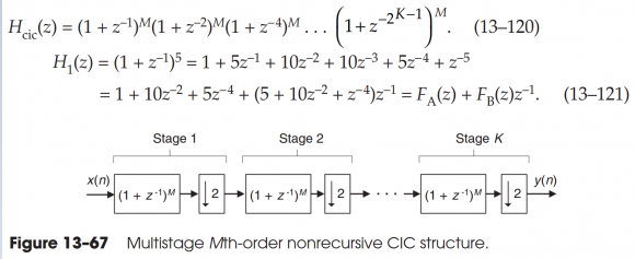
In the Figure 13-67,
Stage 2, (1+Z-1)M is not correct, (1+Z-2)M is correct, and
Stage K,(1+Z-1)-M is not correct, (1+Z-2K)M is correct.
Am I correct?
Hello herbertLu,
the advice I give to folks using the CIC filter is to not use the CIC filter. The integrators in the CIC are large and operate at the highest input frequency. A standard polyphase low-pass filter will perform the same filtering task with less energy and without the need to correct for the sin(x)/x spectral tilt. See attached. I presented it at a conference with emphasis on CIC filter applications. My position was that it is not a good idea. I won over a number of reluctant converts!
fred h

Very nice fred!!! I laughed out loud at all the intro slides. Yes CIC very bad with floating point. I believe with fixed point we can overflow once with no consequence within the range of the subsequent subtraction (as long as we wrap on overflow due to the modulo math it's no consequence). For me, the "multiplier-free" was always a good seller for the CIC along with what for many cases becomes a trivial 3 tap FIR for inverse Sinc compensation (which can also be done to some limits with no multipliers).
So, here you are showing an approach to the polyphase with no multipliers but I couldn't find the specifics of that in the presentation (I looked quickly through it, did I miss it?). That typically wouldn't be the case for a polyphase; what was the trick to restrict it to a no multiplier solution? Just careful down-selection of what we can get with possible shift-scaled coefficients or something more than that? Also cool (hah!) that nothing then runs at the input rate, very nice.
Dan,
Traditionally the CIC is used to filter the output of a 1-bit ADC. There are no multiplies in a FIR filter operating on a 1-bit sequence. Thus a FIR filter can do the filtering with only adds or with short look-up tables. The best example is the use of the CIC to filter the 1-bit sequences in the cell phone. I had advised someone at Qualcomm to drop use of the CIC and contributed a number of filter structures that performed the same task with less energy and less real-estate. It was fun to do that. Ads by Qualcomm showed the reduced in-band ripple of those designs compared to competitive chip designs (which we were sure used the CIC)
fred
Ah ok! Good clarification- that makes a lot of sense. So in applications where down-sampling is to be done on a multi-bit signal, perhaps the CIC is still a viable contender for consideration and we don't have to put it out in the shed yet?

Hi Fred, Dan,
Single bit case is very limited. For very high rate conversion on multibit data you need massive memory to store the coeffs of a sharp cutting filter which could be in hundreds or even more than a thousand though you need few coeffs to multiply per polyphase. In such case CIC filter + sinc correction is a good choice and is mandatory if there is lack of memory resource.
I agree with you that the CIC still has viable applications but don't agree that "single bit is very limited". In particular we are seeing more and more single bit cases as sigma delta implementations where we get the benefit of reduced pin count as could be done if rates allowed with a serial converter interface, combined with the benefits of noise shaping. I may have reviewed it too quickly, but I think fred has shown here for these single-bit cases, since the memory requirement is significantly reduced, that not using a CIC provides a clear advantage overall in terms of resources to implement (ultimately chip size and power). His presentation is worth a detailed look.
Very appreciate for your reply.
I had read the attached rapidly, this's a new topic for me.
I will hard study it.
The z^{-1} blocks shown represent a one sample delay for the sampling rate of that block. With that view, they are all correct as Mth order CIC decimate by 2 filters.
Be sure to confirm that your effective filtering overall surpasses the order of your Sigma Delta modulator (the Sigma Delta modulator has noise shaping going up by 3+6N dB/octave where N is the order of the Sigma Delta), so you'll want a low pass that is going down steeper than that.
Thanks for your reply.
I am thinking in the wrong direction.
I think:
(1+Z^-1)^M*(1+Z^-1)^M*...*(1+Z^-1)^M not equal to the Eq. 13-120.
I am wrong.
Does the key point is stage n's z transform?
What's the z transform of the stage n?
I don’t think you are necessarily “wrong” in your thought process - it is just a matter of being clear on how the frequency axis is scaled. Each block on its own is typically presented as drawn but must be made clear that we have rescaled frequency accordingly from that we have used at the input.
If we want a frequency response of the whole system, referred to the input rate alone (or the output rate alone) then we must change z^{-1} accordingly (such as z^{-2} if the rate is double from our denotation of what the sampling rate is, or z^{-1/2} if our rate is halved). This will then accurately predict the cascaded frequency response but I must also note that we also need to consider the effects of aliasing.
The frequency response for a first order CIC is identical to that for a moving average (so 1+z^(-1) for decimate by two). As we increase the order we simply convolve the [1, 1] coefficients; so would be [1 2 1] for a 2nd order. Interestingly we see how as M increases the coefficients approach that for a Gaussian filter! (White noise at the input will not be spectrally shaped as a Gaussian in frequency due to the aliasing of that noise, but a signal component in the first Nyquist zone of the output will be.
Your explanation is very clear.
When decimation M,
1. must be considered aliasing
2. if M=2, z^(-1/2) instead of z^(-1)
3. M=2, H(z)=1+z^(-1) is moving average filter
4. Order increase, 1+z^(-1) moving average filter become to (1+z^(-1))^M Gaussian filter(the White noise is a very good point of view)
And I study the Multirate Systems and Filter Banks by P.P. VAIDYANATHAN,
the decimator Z transform is X(Z^(1/M))
Thank you very much.


