


The Anatomy of a Finite Impulse Response
As soon as my early adulthood passion for electrical engineering re-asserted itself, post-retirement, and after decades of teaching and researching physics, I found myself bewildered that I did not really understand how FIR filters attain their frequency response! True, the discrete time Fourier transform (DTFT) math for calculating the response is straightforward to use. But the summing of complex sinusoids of different phase responses, as produced by individual impulses in the finite impulse response, did not cater to an intuitive understanding of the process.
Upon investigating the matter, I was eventually led to an intuitive (and satisfying) formulation for the FIR filter theory (see my full article here). In this formulation, any general finite impulse response is re-written as being composed of symmetric and anti-symmetric components. This of course is well-known and, in-itself, is not all too illuminating for my purpose. Rather, the crux of my newly found intuition is this: the symmetric and anti-symmetric IR components are each to be further deconstructed into pairs of impulses symmetrically oriented on each side of the center of the impulse response, spanning the length of the IR (I call these doublets), with the central impulse of an odd length symmetric impulse responses remaining unpaired (I call this a singlet), and the central impulse of and odd antisymmetric IR being zero. These singlets and doublets of impulses produce frequency response elements that are intuitive to understand, easy to visualize and straightforward to combine.
To illustrate this further, let us consider the case of an IR having an odd length (M+1), with the central impulse having the index M/2. Let n be the index of the causal impulses in the response (i.e. n=0 to M). Let N=abs(n-M/2) be the index separation of each element in the impulse pairs relative to the central impulse, with the range of values N=1 to M/2. There will be three unique elements of the general impulse response:
1) Symmetric Doublets having the form and response:

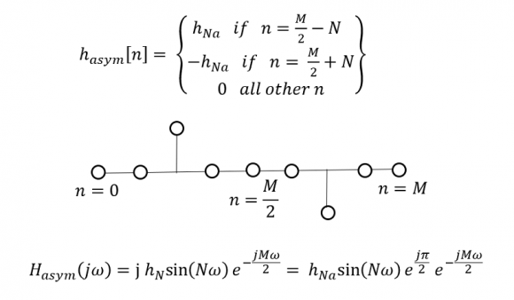
2) Antiymmetric Doublets having the form and response:
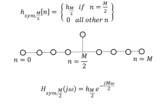
3)A Singlet having the form and response:
Dear readers, I have been away from electrical engineering for the best part of four decades. I have missed out on a lot of development in digital filtering. I tried doing my homework, where it is likely I missed something. So, please forgive me if all this is already known to you.
Thank you for your consideration and your time.
Safwan Arekat

The intuition of converting the symmetric or antisymmetric coefficients to real sinusoidal components is helpful for the large subset of all possible FIR filters that are linear phase. Not all FIR filters are linear phase, so for me I got a lot of intuition for the frequency response of FIR filters, as well as the Fourier Transform (since the response is the Discrete Time Fourier Transform of the coefficients) as well as many other operations in signal processing by thinking of individual frequencies as rotating phasors (complex signals) rather than sinusoids. A unit delay given as $z^{-1}$ is such a complex phasor; just in the frequency domain instead of the time domain: the frequency response of $z^{-1}$ is a constant magnitude for all frequencies and a phase that goes negatively from 0 to $-2\pi$ as the frequency goes from DC to the sampling rate: a “rotating phasor”! $z^{-1}$ rotates once over this frequency span, $z^{-2}$ rotates twice, $z^{-3}$ rotates three times, etc. I have a graphical demonstration as this also leads to wonderful intuition on frequency response for FIR filters for the generalized case of non-linear phase filters.

I really don't see any need to go for doublets/singlets or phasors. The DFT model works and is useful both for amplitude or phase response of any system. It is well established with no surprises. My intuition concern is as below:
Once somebody asked (possibly on this forum) how does a filter "know" where to cutoff. I am still puzzled. The DFT says that but it does not give intuitive explanation.
Hi Kaz. Granted, in digital filtering, there is no alternative that comes even close to the DTFT model. I never claimed this. But I was just trying to re-arrange it so it was less abstract and more permitting of visualisations. One great appeal of engineering is it still allows for a good deal of understanding and intuition (much more than quantum physics for example). So I guess it is still helpful to milk this intuition for as long an possible, because I believe the future is surely headed more towards the absract.
I will be trying hard to see if your model or Safwan's model help me better in visualising the mystery of "how does a filter know where to cutoff". Apologies if this reply is misinterpreted.
Nice question Kaz! Is “The frequency response is the Fourier Transform of the Impulse Response” an insufficient intuition for you? Perhaps then more intuition on that relationship specifically would help?
I tried more intuition with phase. Split up a filter into several filters each with one coeff (rest zeros), input a single tone at chosen frequency and see how final adder adds phase, thus it is this net phase that determines the response at any frequency, try Octave it is free. This approach just helps visualisation nothing more, DFT stays the captain tool and is just doing that in one go:
f = 0.1; %F/Fs
h = ones(1,4)/4; %filter
x = cos(2*pi*(0:100)*f); %input tone
y(1,:) = filter([h(1) 0 0 0],1,x); %first filtering
y(2,:) = filter([0 h(2) 0 0],1,x); %second filtering
y(3,:) = filter([0 0 h(3) 0],1,x); %third filtering
y(4,:) = filter([0 0 0 h(4)],1,x); %fourth filtering
plot(y.');hold
plot(sum(y),'k-') %final filter
individual filters in colour, final sum black
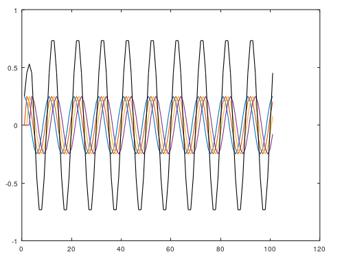
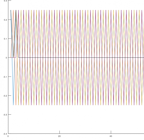
try other values of (f) including Nyquist as below.
Hi Kaz, For some reason I was unable to edit my post here. Maybe because of the figures. Please inspect the attached file IR Example.pdf , it has an example and discussion that might be helpful for answering your question about the cutoff frequency.
regards
Safwan
Thanks Safwan,
I am a bit unsure about your idea in principle. You do DFT to get three responses then you add them up. yes it will do but Why not just do one DFT on whole filter and you are done.
And if you use Octave(or Matlab), freqz(h) will do it all, amplitude and phase. It is based around DFT at chosen frequency grid, range...etc.
The question about "how a filter knows its cut-off" was just my metaphor.
Kaz
Hi Kaz. Wholeheartedly! When concerned with obtaining the frequency response of an FIR, say for an engineering project, I myself have used nothing but the complex DTFT - just as you have prescribed! But I am also a retired professor. I know first-hand the kind of questions smart students might ask requiring intuitive answers. Like the question you sounded earlier about cutoff, or maybe what makes the magnitude response flat in the pass-band. At such a time, I know I would be able to give convincing and appealing answers by doing the extra effort with the doublets. I do not see the complex DTFT capable of doing this in a single pass.
Take care
Hi DanBoschen, The complex phasor concept, with n-fold whole rotations depending on z^-n (I did not realize this), surely adds the dimension needed to cover asymmetrical impulse responses. One would need a good visualisation ability to analyse multiple phasors simultaneously, though. But this will definitely help understand the formation of passbands at frequencies (or angles) where phasors are aligned in the same quadrant in the circle. Or stopbands where phasors are anti aligned in opposite quadrants.
Thank you so much for offering this extremely valuable insight. Can you please provide a link to your graphical demonstration.
Thanks yes I can't underline enough how much visualizing phasors and working with complex signals simplifies the intuition for DSP. My courses start with this in mind and getting past any confusions with that construct. Below is an example of my graphical demonstration (it's on my to-do list to add a Blog Post here including all the explanation around this as well its other mode going from frequency to time to explain the inverse DFT).
Below is a simplest example where we see the coefficients of the filter on the left here as unity gain coefficients (simply a 4 sample moving average FIR). This is the impulse response of the filter. On the right is the magnitude and phase of its Discrete Time Fourier Transform (as the continuous line shown, which is the Frequency Response). In the middle we see the four resulting phasors given by the filter as simply $1 + z^{-1} + z^{-2} + z^{-3}$, consistent with my description you are seeing a phasor that doesn't rotate (1 at angle 0) added to a phasor that rotates once consistent with the $z^{-1}$ term, etc. It's really fun to play with other actual values, both real and complex and leads to a lot of other intuition about the standard filter topologies.
I'm disappointed however as it appears the animated GIF when pasted in the reply here doesn't animate? If that is the case, here is a link to an animated version:
https://twitter.com/DanBoschen/status/165815256974...
Wow! Did not know you could do that on twitter. So, your demonstration even corrected what I said earlier! The phasors do not need to be anti-aligned for quenching at zeroes. Rather, it is sufficient for the vector diagram to be a closed one. That ties in nicely geometrically. Great demonstration. Thank you, and wishing you the best in your project.
Safwan


