


Hi All,
FIR Pre-add (folded) structure is useful to save multipliers. I can see no problem with pre-add direct FIR structure as all that is needed is fold the data pipe on its centre and add up input stages into multipliers.
However, the transposed structure has no pipe to fold. I tried to work around that and found a method that needs plenty delay stages on the output per each multiplier output, in effect (post add). It saves multipliers though.
It would be useful for our system to use transposed structure as it has least latency(input to output) but losing pre-add advantage is a problem.
Any thoughts please?
Kaz

Have you considered transposing folded structure? Take the folded linear phase FIR filter and reverse all direction flows, change the adders to branched and branches to adders. It should have the same number of multipliers and adders

Sorry I don't get it. Do you have any diagram for your plan?
I am talking about transposed structure already and how to exploit filter symmetry when transposed. The transposed structure does not have pipe for input stages as it is based on wiring incoming input to all coeffs + reversing coeffs and adding all sum of products in a cascade with a delay stage per tap multiplier result.
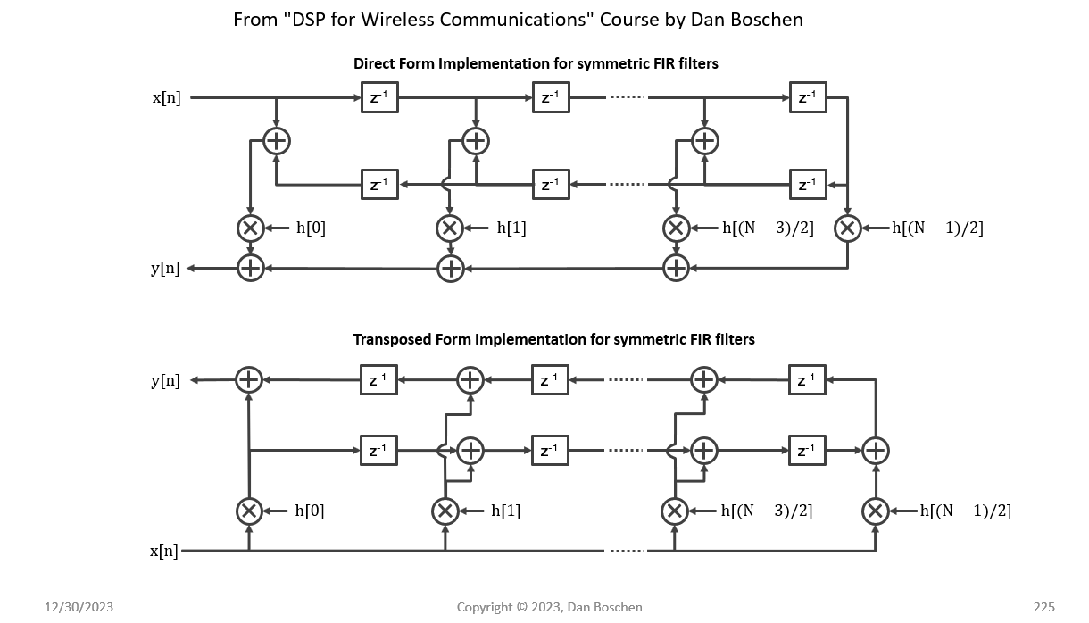
Here's an image of the folded linear phase filter in direct form and transposed form:
Thanks Dan,
That makes sense as output pipe is folded with post add. I arrived at equivalent diagram from concepts in Weetabixharry code.
It is for 7 taps. The dashed boxes are optional timing registers balanced across all paths.
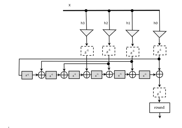

In the transposed form, we multiply the same input data value, x[n], across all the coefficients {h0, h1, ..., hn-1}. If any of the coefficients are the same (like in a symmetric filter), then just compute that multiplication once and re-use the result.
For example, if h0 = hn-1, then don't compute both h0*x[n] and hn-1*x[n] because they're both the same thing. Just compute it once and re-use the result.
That is not right. If h0 = hn-1 the input stage that corresponds to these two coefficients is not same.
Which part is not right? Are you saying that if h0 = hn-1, then h0*x[n] is not equal to hn-1*x[n]?
x[n],x[n-1],x[n-2], x[n-3],x[n-4],x[n-5]...
h0, h1, h2, h3, h4, h5...
if h0 = h5 then xn /= x[n-5]
Are you now thinking about a direct form FIR filter? Your question was about transposed form.
No, the transposed structure is meant to be equivalent to direct or any other structure. The viewing of input stream versus coefficients is same in all cases.
No, they are different implementations of the same mathematical function (a linear convolution). Let me write some rough MATLAB code to clarify...
This is some very rough code, but it shows the difference between direct form and transposed form (and how to exploit symmetry differently in each case).
The interaction of the input data stream with the coefficients is totally different between the two implementations. Direct form looks roughly like your sketch above (except the filter coefficients should be reversed -- but this makes no difference in a symmetric filter). In transposed form, a single input sample is broadcast across all the coefficients in parallel.
close all; clear all; clc;

% Generate a symmetric filter
Nh = 32;
h = randn(ceil(Nh/2), 1);
h = [h; flip(h(1:floor(Nh/2)))];

% Generate some input data
Nx = 1024;
x = randn(Nx, 1);

% Filter (direct form: general)
xpad = [zeros(Nh-1, 1); x];
y0 = zeros(Nx, 1);
for i = 1:Nx
    y0(i) = flip(h).' * xpad(i+(0:Nh-1));
end

% Filter (direct form: symmetric)
y1 = zeros(Nx, 1);
for i = 1:Nx
    % Exploit filter symmetry with pre-add
    x_pre = xpad(i+(0:floor(Nh/2)-1)) + xpad(i+(Nh-1:-1:Nh-floor(Nh/2)));
    y1(i) = h(1:floor(Nh/2)).' * x_pre;
    % If the number of taps is odd, then add the center tap separately
    if mod(Nh,2) == 1
        y1(i) = y1(i) + h(ceil(Nh/2)) * xpad(i+floor(Nh/2));
    end
end

% Filter (transposed form: general)
y2 = zeros(Nx+Nh-1, 1);
for i = 1:Nx
    y2(i+(0:Nh-1)) = y2(i+(0:Nh-1)) + h * x(i);
end
y2 = y2(1:Nx);

% Filter (transposed form: symmetric)
y3 = zeros(Nx+Nh-1, 1);
for i = 1:Nx
    side = h(1:floor(Nh/2)) * x(i);
    % If the number of taps is odd, then add the center tap separately
    center = [];
    if mod(Nh,2) == 1
        center = h(ceil(Nh/2)) * x(i);
    end
    y3(i+(0:Nh-1)) = y3(i+(0:Nh-1)) + [side; center; flip(side)];
end
y3 = y3(1:Nx);

% Check against MATLAB's filter() function
ycheck = filter(h, 1, x);

error_0 = max(abs(y0 - ycheck))
error_1 = max(abs(y1 - ycheck))
error_2 = max(abs(y2 - ycheck))
error_3 = max(abs(y3 - ycheck))
I see your code working.
Your main statement is this post-add of flipped side:
y3(i+(0:Nh-1)) = y3(i+(0:Nh-1)) + [side; center; flip(side)];
Can you, please, translate that to a diagram on the transposed structure for FPGA/ASIC platform away from software loops. I already done post-addition with delay that works but it consumes too much registers.
I could translate it into many diagrams, but the right diagram depends heavily on your application.
What is your throughput requirement? To what extent do you need to optimize for timing performance? Or resources? Or power? Or development effort? Do you need to support multiple channels (TDM)? What FPGA(s) (and, in particular, which DSP slice architecture(s)) do you want to target?
If you are targeting very high throughput (sample rates greater than the clock frequency), then the way we optimize symmetrical transposed form filters in that case is totally different. If you are targeting very low throughput (significantly lower than the clock frequency), then everything is different again.
ASIC implementation is an easier place to start because you don't need to think about DSP slice architectures. But, in general, ASIC/FPGA implementation is a deeper question that would be difficult to answer in a reasonable amount of time.
Thanks, I got the idea now. I have this code (without output loops) that emulates the implementation directly(for even case):
clear;
pkg load signal
x = round(2^10*randn(1,1000));
h = round(2^10*fir1(7,.3));
for i=1:1000
for k = 1:4
xh(k,i) = x(i)*h(k); %mults
end
end
%output cascade
y = [0 xh(1,1:end-1)]; %1,2,3,4,/,4,3,2,1
y = y + xh(2,:);
y = [0 y(1:end-1)];
y = y + xh(3,:);
y = [0 y(1:end-1)];
y = y + xh(4,:);
y = [0 y(1:end-1)];
y = y + xh(4,:);
y = [0 y(1:end-1)];
y = y + xh(3,:);
y = [0 y(1:end-1)];
y = y + xh(2,:) ;
y = [0 y(1:end-1)];
y = y + xh(1,:);
y = round(y/2^11);
yref = round(filter(h,1,x)/2^11);
subplot(2,1,1);plot(yref,'-');hold; plot(y,'g--')
subplot(2,1,2); plot(yref-y)
Let me recap:
Your plan is very helpful. For symmetrical 8 taps the input first enters 4 taps then same input is meant to propagate through the other side arriving at same coefficients in reverse.
The output delay cascade can now be lengthened to apply delays as if last coeff is h0 and advance towards h7 using just 4 multipliers.
Thanks again for your thoughts.


