


I came across an application note from xilinx dated back to October 29, 2008 titled "3GPP LTE Digital Front End Reference Design" from Helen Tarn, Ed Hemphill and David Hawke.
In the note, they have used half band filters for upsamplng by 2 and mentioned doubling the gain of these half band filters in order to adjust the overall gain as when upsampling every other sample is zero. When I tried to double the gain by multiplying the impulse response by 2, the resulting gain of the pass band increased above 0 dB.
Is the doubling really needed here if yes, what is the correct procedure to double the gain of the filter?

In the traditional method of interpolation by integer K, by inserting (K-1) samples in between each original input sample, there is an output amplitude loss by a factor of K. What practitioners usually do is multiply their FIR filter's coefficients by K to compensate for the gain loss.
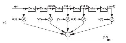
Here's a traditional 6th-order half-band filter (from Chapter 5 of my DSP book).
Instead of computing all output samples and discarding every other output sample, it's better to input two samples before computing a single output sample. That way your decimation-by-two system requires fewer computations per output sample!
Now a Xilinx method of interpolation may be "nontraditional" and already have the gain loss compensation built-in in some way. Which means when using their interpolation method you need not worry about gain loss. LabPe43, apply a low-frequency sine wave, whose peak amplitude is one, to your 'interpolation by two' system. Then see if that sine wave shows up at the output of your interpolator with a peak amplitude of 1/2 or one.That will tell you the passband gain of your interpolation system.
By the way, regarding half-band filters, you might be interested in the material at:

If by "here" you mean "in this problem", yes, if you want to keep the same overall gain. If by "here" you mean "in the filter coefficients", then probably not. Instead, you can do the job and then "double" after the filter.
However, you want the filter's passband gain to go up, because when you upsample by inserting zeros the effective gain of the operation is \(\frac{1}{2}\).

I really like Tim's answer.
I would like to add a couple of ideas related to the filter design.
A typical implementation would use a polyphase decomposition of the filter coefficients. For Xilinx, this would be logical, because in hardware, you would never insert zeroes, but rather use the same data twice - by applying two separate sets of coefficients - before shifting a new sample into the delay line.
Some filter design programs might apply the needed gain to the coefficients during the design.
Since we are interpolating (DC allowed through too), you might try simply adding up the alternate coefficients in the full filter design, or the two sets separately - if already "polyphased" - to see if the DC gain is 1.0, as it should be, and adjust if needed.
David
As an added bonus, if you design it right a half-band filter is zero on every other tap except for the center tap, so the math is reduced even further. I'm trying to work out in my head how the filter would look in hardware, and at least partially failing -- but you will be able to dramatically reduce the computational load by using a proper half-band filter instead of an "any old" filter.
Thank you all very much for clarifying my confusion regarding filter gain.


