


Pardon me if my question is very basic.
I would like to know why in the design of an Filter in Matlab, one has to specify sampling frequency.
It looks like the cut-off frequency is defined in terms of sampling frequency. Below is a Matlab sample for an FIR filter:
f1 = 10000;
f2 = 15000;
delta_f = f2-f1;
Fs = 192000;
dB = 40;
N = dB*Fs/(22*delta_f);
f = [f1 ]/(Fs/2)
hc = fir1(round(N)-1, f,'low')

Any digital system has no sense of time until clock is applied to sample the signal.
So is matlab, DSP, FPGA, ASIC etc. cutoff is relative to Fs as ratio.
Unfortunately many people code things with explicit time vector which I see it misleading and meaningless so far.
Kaz

Sharan123, the code you posted does two things: (1) it uses an empirical formula to compute a rough estimate, N, of how many coefficients (taps) are needed by a lowpass FIR filter when the lowpass filter's cutoff frequency is 10 kHz, the filter's stopband begins at 15 kHz, and the filter's input sample rate is 192 kHz. Your computed value for N is N = 69.8. Because the fir1() command, which computes your filter's coefficients, needs an integer number to define the number of coefficients, you rounded N up to 70 so that your final fir1() command becomes:
hc = fir1(70-1, f,'low') = fir1(69, 10000/(192000/2), 'low')
= fir1(69, 10000/96000, 'low') = fir1(69, 0.1042, 'low')
Because of the way MATLAB software was designed, that 0.1042 value tells the fir1() command that the cutoff frequency of your lowpass filter is defined by you to be 0.1042 times half the filter's Fs input sample rate. That cutoff frequency, then, is 0.0521 times the Fs sample rate (defined by you as 192 kHz).
The 69 in the fir1() command tells MATLAB you want to compute the coefficients of a 69th-order FIR filter, which will have 70 coefficients (70 taps).
Sharan123, READ THE FOLLOWING:
Regarding the word "frequency", if I drew a time-domain sine wave sequence having EXACTLY 10 samples per cycle for you and asked you, "Sharan123, what is the frequency, measured in Hz, of this sine wave?", what would you say? After thinking for a while you should say, "I will not know the frequency, measured in Hz, until I know the time period T (measured in seconds) between each sample (where T = 1/Fs)." And if I then told you that T = 0.25 seconds you'd know that 10*0.25 = 2.5 seconds is the period of the sine wave so then it's frequency is 1/period = 1/2.5 = 0.4 Hz. Thus you needed to know Fs (measured in Hz) before you can think about a sine wave sequence's frequency measured in Hz.
If you want to know the spectral content of a digital signal, measured in Hz, you MUST know the Fs sample rate of that signal! In the analog world there are two ways to quantify the notion of frequency; cycles/second (Hz) and radians/second. In the world of DSP there are many ways to quantify the notion of frequency. For more info on this, see:
https://www.dsprelated.com/showarticle/199.php
Dear Rick, Michael, Fred, Kaz,
Thanks. I really appreciate your inputs. I think I am clear on the original question. At least, I have lot of input for consumption.
One more question that came to my mind while running the code I posted.
Please see the snippet below.
N = dB*Fs/(22*delta_f);
I was thinking, assuming Nyquist rate is met, is sampling frequency a good thing or a bad thing. FOr example, in the above case, if Fs was very high then N too would be high, resulting in higher filter latency and cost of constructing in HW would also be high. So, are we better to make sure that we sample just enough to be able to resolve the highest frequency and anything more than that comes at a cost.
Your thoughts please ...
Sharan123, whoa, wait! You wrote, "...if Fs was very high then N too would be high,...". What you should have written is, "...if the ratio of Fs/delta_f was very high then N too would be high." With tapped-delay line FIR filters, what has the greatest effect on the size of 'N' is the ratio of the data sample rate (Fs) over the filter's transition band width (delta_f). For lowpass filters my phrase "transition band width" means the frequency where the stopband begins minus the passband cutoff frequency.
So,... if the transition band width is narrow relative to Fs then N will be high. To quote Forrest Gump, "And that's all I have to say about that."
Dear Rick,
Keep design parameters same in the above equation, can I not Fs independently? This is the case I was referring to when I said increasing Fs
f1 or f2 also change with Fs and proportionally
kaz
Hi Kaz,
I don't understand what you mean by f1 and f2 change with Fs. Typically, these are independent parameters I start with irrespective of Fs. Can you please elaborate, preferably with an example?
There are two perspectives (and this can cause confusion)
1) you are in digital domain(Matlab) then you apply Fs on your digital stream (x input of a filter) then any frequency in x will be determined by applied Fs.
2)your perspective is an analogue signal digitised at an ADC with selected Fs but fixed analogue frequency. Then if Fs is high relative to cutoff point it requires larger N
Kaz
Sigh! Why I did not think about this earlier. Yes, I was referring to sampling an analog signal when I referred to Fs.
Sharan123, please clarify you question, OK?
Dear Rick,
Case 1: f1 = 10000; f2 = 15000; Fs = 192000
Case 2: f1 = 10000; f2 = 15000; Fs = 384000
My design parameter remain the same in case 1 and case 2. In case 2, I decide to sample the signal at twice the rate.
Given this, the N below would be twice that of case 1
N = dB*Fs/(22*delta_f);
Higher Fs but same absolute cutoff means sharper filter and hence larger N
Kaz
Sharan123, you wrote:
"Case 1: f1 = 10000; f2 = 15000; Fs = 192000
Case 2: f1 = 10000; f2 = 15000; Fs = 384000
My design parameter remain the same in case 1 and case 2."
That's not correct. Your filter transition band width *RELATIVE TO FS* is different in the two cases. Remember, transition band width is interpreted by MATLAB as the ratio (f2-f1)/Fs.
Dear Rick,
I am still trying to wrap my head around the equation and what you mention about the transition bandwidth being ratio of (f2-f1)/Fs
N = dB*Fs/(22*delta_f);
So, if I kept f1 = 10000 and f2 = 15000 and instead of having Fs = 192000, I changed it to Fs = 384000, what would be implications to the above equation?
Would N change, would meaning of f1 and f2 change?
In my view, there is nothing sacred about Fs = 192000.
So, we picked up f1 and f2 as frequencies of our interest and then with Fs = 192000, we used the above equation to find N.
Now if we initially started with Fs = 384000 then how would we know what values would f1 and f2 would be interpreted as?
Let's change that equation to the product of two ratios, as:
N = (Fs/delta_f) * (Atten(dB)/22).
Looking at the first ratio, Fs/delta_f, let's say delta_f = 15 kHz -10 kHz = 5000 Hz. So the first ratio becomes Fs/5000. So now,...how does that Fs/5000 ratio change if you double Fs? The value of that ratio will double!! The f1 = 10 kHz frequency value did not change and the f2 = 15 kHz freqency value did not change!Let's say, a system engineer asks you, "How many coefficients (taps) are needed for a digital FIR lowpass filter if the filter's passband ends at 10 kHz, the stopband begins at 15 kHz, and we need 66 dB of attenuation in the stopband?" On your white board you write: N = Fs/(15000-10000) * (66/22) = Fs/5000 * 3 = 3*Fs/5000
The sys engineer then says, "Fs = 192 kHz." Now you say, "In that case N = 3*192000/5000 = 115.2 so you'll need approximately a 115-coefficient FIR filter."
Then the the sys engineer days, "Oh wait, ...I was wrong. My Fs is actually 384 kHz." Next you say, "In that case N = 3*384000/5000 = 230.4 so you'll need approximately a 230-coefficient FIR filter." Next the sys engineer asks you, "For this 230-tap filter, will the passband still end at 10 kHz and the stopband still begin at 15 kHz?" You will then say, "Yes, of course. I did not change the delta_f = 5000 value when you doubled the Fs value."
Sharan123, I hope what I've written makes sense to you. I cannot think of a simpler way describe the meaning of the 'N = dB*Fs/(22*delta_f)' equation.
Dear Rick,
Thanks. I want to clarify on your explanation.
So, in the above example, f1 and f2 remain same.
Fs is either Fs = 19200 or 384000 KHz.
N is either 115 or 230 taps.
So, given f1, f2, Fs, we are computing N values for Fs = 19200 or 384000?
Sharan123, you wrote:
"So, given f1, f2, Fs, we are computing N values
for Fs = 19200 or 384000?"
Your words are not in the form of a question but you ended your words with a question mark. So I'm confused. Are those words making a statement or asking me a question?
Dear Rick,
Sorry about that.
To summarize, keeping f1 and f2 constant, we are varying Fs and deriving value of N for 2 cases of Fs. Is this correct understanding?
If my understanding correct then my original comment that increasing Fs proportionally increases N is probably correct.
I was thinking, assuming Nyquist rate is met, is sampling frequency a good thing or a bad thing. FOr example, in the above case, if Fs was very high then N too would be high, resulting in higher filter latency and cost of constructing in HW would also be high. So, are we better to make sure that we sample just enough to be able to resolve the highest frequency and anything more than that comes at a cost.

For everyone who might want to know, the Matlab functions are easily reachable on the web. So Google fir1 and the top hit is:
https://www.mathworks.com/help/signal/ref/fir1.htm...
I don't see anything in Matlab fir1 that requires a "sampling frequency". It appears that the Matlab code provided us includes some estimate formulas being evaluated to determine "N" which would be a reasonable thing to do. That's the
N = dB*Fs/(22*delta_f) which isn't a formula that I'm familiar with but must have seen somewhere.
Let's see:
This is a lowpass filter with round(N) -1 coefficients and cutoff frequency of "f" = 0.1 where "f" is computed as a fraction of fs/2 which is always the case for a digital filter of course.
So, the reason for using the sampling frequency is really just a convention that's being used in the estimate for N. It really has nothing to do with Matlab.
From: Rick Lyons at:https://www.dsprelated.com/showthread/comp.dsp/101...
It's a fred harris formula Atten/(22*(Fstop-Fpass)

In this particular example, the person is working in real-world units (as indicated in Tim's response below) to define the parameters of the lowpass filter. The cut-off frequency is 10 kHz and the desired attenuation between 10 kHz and 15 kHz must be around 40 dB. The 40 dB attenuation requirement within the 5 kHz range determines the necessary filter order of 69 (the first parameter in the call to the FIR1 function; which corresponds to 70 filter coefficients).
The FIR1 function uses normalized frequency units to define the cut-off frequency or frequencies of the filter being designed. As a result, for this case, the lowpass filter has a 3 dB cut-off frequency of approximately 0.1042 normalized frequency units. This corresponds to the 10 kHz value (i.e. 0.1042 * 192 kHz / 2 -> 10 kHz).
In Matlab you can show the frequency response of a filter using the FREQZ function. If you typically work in real-world units, you can plot the response with frequency units in Hertz.
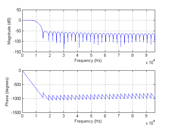
This can be realized using the syntax: freqz( hc, 1, 4096, Fs );
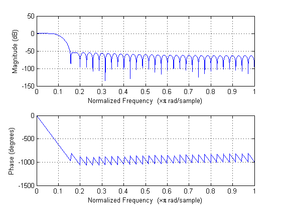
Or normalized frequency units if you prefer, using the syntax: freqz( hc, 1, 4096 );
Since this is a FIR filter, the second argument in the FIR1 function is 1, or unity, since there are no coefficients in the denominator of the discrete-time filter function (which are the a-coefficients). The value of 4096 simply determines the number of points at which the FREQZ function calculates the magnitude and phase response of the lowpass filter response defined by the hc coefficients (which are the b-coefficients).

I'm not familiar with Matlab, but from that code scrap, the 'fir1' routine wants a cutoff frequency in per-sample units. So if you want to specify the filter in per-sample units, you don't need the sampling frequency.
But, if you need to specify the filter in real-world units then you need the sampling frequency.


