


Predicting spectral leackage for unevenly spaced sampled signal
 Started by 7 years ago●17 replies●latest reply 7 years ago●152 views
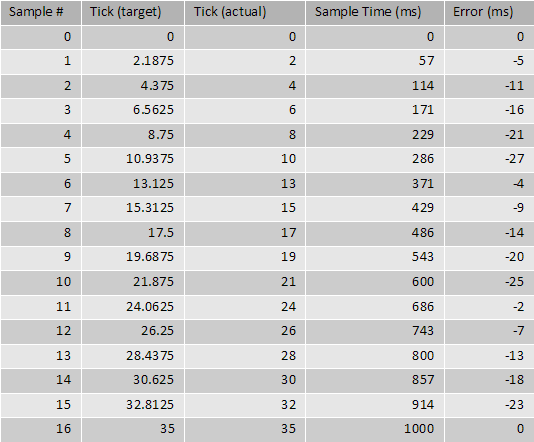
(Updated table, as last two columns had errors)
Now I can simulate this and generate plots form this. I can see that if there is a 3Hz difference between the system clock and a clock being a multiple of the sample rate (i.e. 32Hz) I get components spaced 3 Hz apart. I have the created the following frequency domain plot:
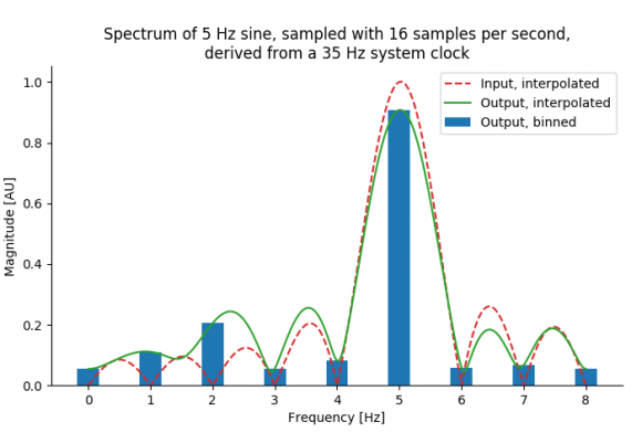
Now I can see sort of harmonic distortions at 2Hz, 1Hz, and 4Hz. However, what I wish to understand is how to explain from input (e.g. the 35Hz system clock, 16Hz sample, 5Hz sine, but could be any), the output spectrum I see and their amplitudes, in an analytical manner. Is this harmonic distortion?
I need to be able to asses in general the implications such a sampling system would have for the over all signal quality without needing to resort to simulation.
Now, I am not a DSP guru, otherwise I might have figured this out myself, but it got me baffled. Can anyway explain this in an relatively easy manner, or point me to sources?
Thanks! Vincent
Hi Vincent,
First, this is not harmonic distortion. The spurious signals you see are phase modulation. The sidebands appear on harmonics because of the numbers you have chosen for the simple example.
The issue here has been faced by designers of frequency synthesizers for years. A phase-locked loop synthesizer can only generate frequencies that are integer multiples of the reference frequency. For instance, with a 1MHz reference frequency the output frequency can only be 1,2,3....MHz. (This is due to the digital divider in the PLL.) But the specifications for the synthesizer might call for 1Hz resolution, so how can we increase the freq resolution without reducing the reference frequency (which unacceptably slows the loop settling time and increases the phase noise?)
There are two major technologies that solve this problem. Look for references on 'Fractional N Frequency Synthesis'.
The first, as has been suggested, is to interpolate the samples. Note that your accumulator has a number that represents the timing error for each sample. In the case of a freq synthesizer, this accumulator number is subtracted from the loop phase error to cancel the spurious sidebands you have observed. In your case you can use this accumulator number to determine the point between two samples at which to calculate a new sample at the correct timing by linear interpolation.
This interpolation will, of course, not provide an exact value, so you will still have spurious signals all be it at a much reduced level. If this performance is not sufficient, you can use a higher order curve fit.
For completeness, the second Fractional N technology is called MASH. It randomizes which sample you take at any given instant. Because the samples are pseudo random, the phase sidebands disappear and are replaced by phase noise.
Finally, to answer your question about how to 'the implications such a sampling system would have for the over all signal quality without needing to resort to simulation.'
The key is something called 'reciprocal mixing' by RF engineers. All this means is that any phase modulation (or if you prefer timing error) on your sampling clock appears as if it is on the input signal. So your Sawtooth modulation due to your sampling technique appears on the FFT as if the input signal has sawtooth phase modulation. The spectrum of a sawtooth is well documented.
Hope this helps,
John

John beat me to it. Some additional points:
- The phase modulation will be different for different frequencies in the input spectra -- a 1Hz input signal will have half the phase modulation of a 2Hz signal, etc. So you can't just calculate the effect at one frequency and assume it's the same for all.
- The good news is that the sampling process is still linear, even if it's adding apparent phase modulation. So you can predict effects on signals more complicated than sine waves. If your input signal has a bandwidth significantly less ("significantly" changes meaning depending on your problem, BTW -- you have to apply common sense) than the frequency of the phase modulation then you can probably treat the problem as if you were working on a tone.
- The spectrum of a sawtooth is well documented, but particularly if the phase modulation is strong enough (I'd say over 1/10th radian, but again, that depends on your problem) then you need to go by the spectrum of a sine wave that's phase modulated by a sawtooth.
Tim, you have some good points.
Also I would add that the linear interpolation I referred to is not resampling by adding zeros and filtering. As Vincent pointed out, this is impractical in this case. However, in this case the interpolation is
Y = Y(n) + (Y(n+1) - Y(n))*A(n)
where A(n) is the fractional accumulator value and Y(n) is the sampled input value at time nT. Easy and fast calculation.
Another subtle point is that this is a sampled sawtooth. Since a sawtooth waveform's harmonics only fall off at 1/n, you can get some bad alias products near the original signal.
John
Thanks for all your replies guys! All in all this is going to take me a bit of time to work out. I'm going to study the pointers you all gave, and if I have questions, I'll come back and ask them. Much appreciated!
Kind regards,
Vincent

Hi John,
Regarding frequency synthesis a third approach is as follows:
In FPGA (and ASICs) frequency resolutions in MicroHz are possible using phase accumulators with high resolution clocked by one clock. There is no interpolation but just phase is added up to point to a sine table. For example if clock speed = 100MHz, and phase accumulator set to 24 bits then the phase is incremented by round(Fo/Fs * 2^24) where Fo is target output frequency.
The result of this accumulator is used to address a sine table. Though rounding error occurs but this is tackled with phase dithering. (such designs may be referred to as NCO or DDS...). The sine table size and bitwidth resolution is a separate parameter(= amplitude resolution)

This problem seems intractable as stated. There is insufficient oversampling to do a decent job of capturing the underlying "signal". There is no mention of a Nyquist filter to prevent splashing for the real-world application. Why not stay in the time domain and do an analog filter and then sample its output if you are resource constrained?
Classical digital filtering (FIR/IIR/DFT) is based on circular convolution, which brings along a lot of baggage with symptoms like Gibbs Phenomenon. Of course if you only have a partial cycle of sinusoid captured, then the phase of the current data is different than the previous one since you can never sample coherently. If continuously sampled, then the pattern repeats at the frequency difference beat. And with noncoherent sampling you get partial steps in DC offset (assuming you started with zero DC offset pure AC signal) that have the spectral effect of an impulse but with most of its energy at the fundamental. Most, if not all, digital filtering can also be likened to an interpolation process: the filter tries to make a signal look like what it wants to see, similar to a projection of a 3d image onto a 2d plane. For example, a DFT tries to make every signal look like a coherent sine wave - it is a projection of the signal onto the DFT's target sine wave. It uses a sinusoidal basis function, and other types of "filtering" that can be done with other basis functions (e.g. Hartley Transform, wavelets).
I recall in my early days of DSP research running across filtering techniques for unequal time spaced samples called a periodogram. This issue turns up in a lot of real-world problems (here are papers to check: https://www.nonlin-processes-geophys.net/18/389/20... and http://webee.technion.ac.il/people/YoninaEldar/Inf...). It was originally for research into a control-motion-noise filter for MLS for data that was not coherently sampled. I ended up getting put on another project.
Thanks for your reply. Please also see my reply to Slartibartfast. The question stated in the beginning was just an example. In reality the band of interest is much lower than the Nyquist. Also we do use analog and digital filters. I'll look up your references. Thanks!
Neither me a dsp half guru but I feel you are distorting your signal then analysing the result of distortion based on "what if" approach. You should create new samples by interpolation rather than repeat some samples. Repetition of each sample (duplication) can be predicted but random repetition need be simulated for each case and neither is good practice
Hi kaz,
Well, yes I am distorting the signal, but I'm not introducing random jitter. Note that this is a sampling system, so the actual input signal is unknown. I'm just trying to analyze the implications, and using a sine to do this.
I'm introducing a predictable (and repeated) phase change. It is a way to approximate a specific sample rate, if that rate is not a divisor of the system clock. Sort of an inverse numerically controller oscillator (NCO).
Here is the error per sample. You'll see it is predictable:
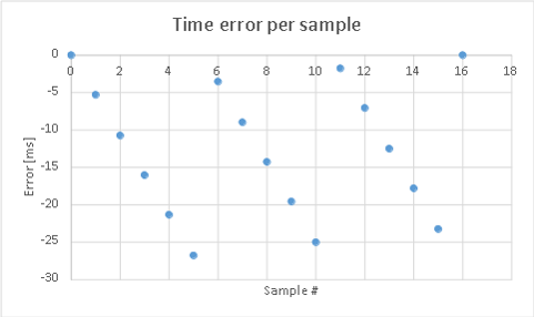
The actual phase change depends on the frequency of the input signal.
It will have repeated phase pattern in your case with regard to duplication of a sample but I see it equivalent to introducing random amplitude error at well spaced phase intervals.
I personally would prefer fractional re-sampling which creates new samples or drops samples without distorting spectrum.
However, if you examine your spectrum and can then filter off the effect of error then it might work for you but it follows the methodology of "Get it wrong then correct it".
I have painted a simplistic view of the system in question for the sake of clarity. Fractional re-sampling will not be possible in our case, as the smallest common multiple will be way to high and the system is quite resource constraint. I do not wish to undo the effects of getting it wrong', I just wish to quantify what 'wrong' actually is in a integral manner.
you might use CIC filter. It requires very low resource if correction filter is not added.
My understanding is that variable sampling from analogue side had been analysed, but in your case the sampling is already done and signal is then passed from its clock domain to the wrong one. You might consider ignoring certain clocks on the new clock rather than duplicate samples and only process enabled clocks.

What is the final end use of the signal? If you are just doing analysis or extracting information from it, then there's no need to insert the zero and generate the associated distortion. If you need to resynthesize the signal later, e.g., for playback at the other sample rate, then a rate exchange filter (aka, resampling filter) can do so without adding unnecessary artifacts from the zero-insertion technique.
I think a complete answer would depend on what you intend to do with the sampled data.
Can't really go into detail here. Signals will be sampled and used in correlation analysis. In reality visible the distortions will not be very high, because:
A) the actual input signals will mostly not be a continues sines
B) The input sampling rate (and Nyquist) is much higher than the output sample rate and the band of interest is small. We actually do use filters to down convert he signal after sampling by the fractional clock divider. There is also an analog low pass filter on the front end, with a -3dB cut off frequency at around 1/25th of our Nyquist.
I am aware that the artifacts generated by our sampling method may not have any impact on the quality of the post-analysis, I do wish to understand them. Its not enough to say 'well, I *think* it doesn't matter'. And to start I need to know the distortions generated by the sampling process itself, though I know many of these components are filtered out, or 'trivial' after down conversion, I wish to know at what level (dBFS) I can expect to see these components back in my band of interest.
I have a feeling I might be surprised that under specific conditions nasty things may happen at amplitudes much higher than anticipated.
If you are just collecting samples and doing some DSP stuff with them, like correlation, etc., is there really a need to resample to the other clock? I'm still not clear on why this is necessary. Even if the processing is done in hardware at the other clock rate you can pause for a clock once in a while and not lose anything, rather than inserting samples that shouldn't be there.
Just trying to understand the system better and make sure a first assumption isn't in the way.
Okay, I think I misunderstood the 'inserting of samples'. I thought you meant 'inserting of additional clocks'. I am not inserting samples. I have a fixed sample rate, but a sample clock which is not a divisor of the system clock. For example, if the system clock is 22 Hz and the sample rate is 10 Hz, for 8 samples the period will be 2 system clock ticks. However in two cases the period between samples will need to be 3 clock ticks, such that the total number of samples is 10 at the end of one second.
So basically samples are taken with a period of 2 clocks, but this period is actually 0.2 ticks too short, causing the sample to be taken 'too early'. So, after 5 clocks I insert an additional clock tick, making one period 3 ticks, such that my error is 0 again. I would do this twice in a second for the case mentioned here.
Ah, I misunderstood. That happens a lot. ;)
There were a lot of papers on non-uniform sampling probably ten years ago, and my impression on the gist of the results was that it's basically a pain in the butt. There are some limited areas where it can be useful, but is otherwise probably best avoided because of the issues.
There are techniques for resampling a non-uniformly sampled sequence into a uniformly-sampled sequence, as long as you know when the sampling times were. Like most things this costs some processing overhead, but at least you'll know what you have and will be able to separate actual effects from artifacts.


