


How to downconvert a Complex RF signal in Matlab?
Hi All,
I was trying to simulate a digital communication model with a complex rayleigh fading channel in Matlab.
The Data is BPSK modulated and is multiplied with a sine wave of frequency Fc for upcoversion of baseband signal to passband.
My doubt is, once the signal is passed through the channel the received signal will be a complex signal. Hence if I were to downconvert and pass it through a single channel ADC, what will the output be and how will I get it in Matlab?
Any help will be really appreciated!
Thanks in Advance!
#wirelesscomm #matlab

RF data i.e. passband data is never complex, it is real. It becomes complex only when you down convert it to baseband(using 2 ADC i.e. two channels).
In MATLAB simulations, we rarely go to passband. We work with baseband simulation i.e baseband transmitted signal, baseband channel model and then baseband received signal. of course filters are also baseband.
If this does not reply your query, could you please put more detail, may be with diagram etc.

You have already been answered but I will just confirm that in modelling tx/Rx chains in matlab you can:
1) model DAC by just truncating or rounding your tx output to DAC bitwidth
Obviously there is nothing analogue in such model though you can add noise, interferers etc.
2) model ADC by just accepting the above signal stream as is plus add your favorite noise. In reality the ADC phase could be anywhere but to model that is sheer fun e.g. you can model fractional phase by upsampling your signal 1000 times then pick at random one sample anywhere between sample 1 to sample 1000 and repeat every 1000 samples.
3)high frequencies in Matlab can only be a max of Fs/2 and Fs in Matlab is just 1 i.e. max frequency will have two samples per cycle. If you assume Fs > 1 then you are just faking high frequency and will need to match baseband sample rate accordingly.
For actual RF frequencies you will need hundreds or so of samples per cycle relative to baseband. This is not always practical and in fact not needed as one can assume upconversion/downconversion need not be modelled.
The signal once modulated by RF carrier will be real.The channel also will be real and pass band.There will be a single ADC with real output.You can down convert and give base band which is real and taken for further processing.
If you use QPSK/QAM etc then complex base band will be converted to real data by multiplying real base band with cosine of carrier and imag of base band with sine of
carrier and added.It will pass through real channel and AWGN will be added.In the receiver you need Hilbert Transformer to convert real pass band to complex base band.this complex base band will be used for further processing.

Rayleigh fading channel models may be complex, (as are many channel models), but usually they are applied at baseband. In a simulation the upconverter and downverter may be considered lossless and distortion-free, and are therefore either often skipped or their distortion effects are applied at baseband with the rest of the channel model. In other words, many communication simulations with channel models are done completely at complex baseband and skip the upconversion and downconversion processes. This allows the sample rate to be kept much lower and therefore the execution time of the simulation is kept much faster.
As others have said, the actual channels between antennas are all real-valued, but may have phase distortion effects that can be easily modeled at baseband with complex-valued models.

What Eric is saying (if it's not clear) is that if the Rayleigh fading channel model is complex, it's implicitly modeling the up- and down-conversion, and acting on the baseband signal.
I.e., it's telling you what you'll get out of your downconverters given the channel and what you put into your upconverters.
Hi All, Thanks for shedding some light into my query.
I have got the most of it, what you guys mean, and I appreciate it, but still have some bits left.
I am using an upconverter (by multiplying with a sine carrier) and a downconverter ( by multiplying with a sine and a cosine carrier) just to receive the signal as a complex baseband.
The baseband signal I am transmitting is real and I am further adding an complex rayleigh fading channel (with some delay spread resulting in few taps for the channel).
On the receiver side, what I have is a complex sequence which was a result of convoluting the real signal with the complex channel model.
Now I want some way to make the received signal a complex baseband, which will be helpful for, mapping into a constellation and extracting phase information.
Multiplying the received signal's real and imaginary parts with cosine and sine carrier respectively doesn't do the trick.
Henceforth I am stuck at this point where I am unable to get back my baseband signal.
Any ideas on this or have I gone terribly wrong somewhere?

Hi. I'm sure the guys here can answer all your questions, but they need more information from you M_313. Are you able to post a block diagram here of your digital communication model?
you got complex input and you want complex baseband. just downconvert to dc by mixing with complex cos/sin at -f of your signal centre frequency(f). So what is stopping you?
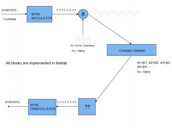
The following is the block diagram for my implementation and I am stuck at the receiver front end marked as "??".
bitrate = 1Hz, then suddenly Fs = 100???
How did move from 1Hz to 100. Did you do upsampling or repeated samples 100 times?
For every bit I have generated 10 periods of sinewave with the corresponding phase([-1, 1] maps to [0, 90 degree phase]).. i.e. bitrate is 1 Hz => Symbol duration of 1 sec => 10 Hz Sinewave will have 100 Samples @ Fs=100 Samples/sec => 10 samples/cycle of sinewave.
ok that is in effect repeat of each bit 100 times then mixing with 10Hz tone.
It should do though in practical systems pulse shaping may be considered to avoid high frequency generation but for your modelling repeating bits is ok.
All you have to do is downconvert to baseband in receiver by mixing with -10Hz. and since you are doing BPSK then you will pick up the two tones as +/- constant(dc) on either I or Q but one channel is enough to check these two states.
By mixing do you mean that i have to multiply "I" with a cosine wave at -10Hz and "Q" with a sine wave at -10 Hz to bring it to +/- DC?
Or is it also possible to multiply with sinewave(like a single LO) to generate one channel at baseband and then further convert to I and Q (say in digital domain) for constellation mapping?
Since you have complex input then apply tone of -10Hz (complex) i.e. do complex mixing.
You can view what is going here as follows:
(1) bits => repeated 100 times (in effect two state dc), call it mapping
(2) Tx mixer, the 10Hz in your case is either real only i.e. it is actually +/-10Hz or complex as +10Hz. If +/-10Hz then you get two side bands, and one should be filtered at Rx. If complex +10Hz then no filter is needed.
(3) at Rx: you reverse mix with -10Hz and you should get the two dc states which is your bits as repeated 100 times.
Then pick up one sample every 100 and you are back to bits (demapping)


