


I'm receiving an AM tone-encoded signal using heterodyne receiver hardware with I/Q output. The second IF frequency is low but still above the modulating tones. Both I and Q are digitized and I use software to demodulate and detect the tones.
I get good results when SNR is 10 dB. Any lower than that and errors appear in the tone detection. I've tried software filtering to improve the SNR but it isn't always enough of an improvement.
Does anyone have suggestions of other ways to deal with a low SNR?
Thanks, Greg

When the SNR is low, where is all the undesirable energy? Is there a flat noise floor that is coming up, or are there specific tones coming from your demodulation algorithm or somewhere else? Any popcorn type transient noise, or is the output consistent? It's probably easier to come up with a tone detector if we know what sort of noise it needs to reject.
While working on an AM receiver a little while back I tried using simple AM demodulators like sum-of-abs only to find that the tones these generated could cause some really strange issues. If your I and Q channels have any gain mismatch, that will cause an undesireable tone as well. The only AM demodulator that worked for me was sqrt(I^2 + Q^2). I've also heard that lower sample rates going into the demodulator (compared to your receive bandwidth) can cause issues. If your sample rate is >10x your AM bandwidth you should be fine. Of course if all your noise truly looks like noise, then these tips won't help you.
Also, I wanted to double check that you are digitally or analog mixing down to zero-IF? If your IF going into the modulator is higher then I'd recommend trying a demodulator sample rate much greater than the IF frequency, or decreasing the IF frequency.
Hi greg... we need some more information... you said "demodulate and detect tones"... "tones" suggests more than one option. Is the tone a single tone with one of two amplitudes, one for a logic 0, and one for a logic 1 (Amplitude Shift Keying, ASK)? Or is it one of two tones at different frequencies , frequency f0 of a logic 0 and frequency f1 for logic 1 (Frequency Shift Keying (FSK)? Is the tone, whichever it is, simply keyed on and off, a rectangular envelope? or is there some other smooth envelope?
I might be able to figure out which option you have by your letting us know what is the demodulation and detection process you are using...can you pass that back to us? sample rate, in samples per symbol would be useful too.
fred

Thanks for the reply, Fred.
Signal is amplitude modulated with single frequency tones that range from 190 Hz to 489 Hz. Each tone burst lasts for 60 msec.
Demodulation of the AM is done by calculating the magnitude of the I/Q complex signal from the tone frequency riding on a 1000 Hz carrier (2nd IF frequency).
Tones are determined using the Goertzel algorithm.
Most of the noise that I've seen is continuous, apparently random and broadband.
Greg
It sounds as if the I-Q down conversion from the first (digital) IF to second (digital) IF centered at 1 kHz i keeping the signal real unless you are using the Goertzel algorithm to perform a set of second down conversions to baseband.. Still need a filter following the down conversions to reduce the noise BW to the tone BW. The filtered data is what you detect (sum of squares) not simply the down converted samples...are you doing this? or do I have a bad visualization of the operations you are doing? If you can, please send the problem statement to fjharris@eng.ucsd.edu and let me see how i would work the problem.
fred

Hi GregLapin. I agree with fred harris. It's easier for people to give you useful suggestions if you post a block diagram of your receiver, and sprinkle your diagram with lots of details like: signal bandwidths, filter cutoff frequencies, digital samples rates (samples/second), etc.
Rick, Fred, and Tim,
Since I am somewhat graphically challenged, let me describe the receiver architecture to you in text and see if that makes it clear enough:
VHF signal is amplified and mixed with LO1 to give IF1 = 243 MHz and bandpass filtered (SAW, BW=50 kHz). The first IF is amplified and mixed with LO2 to give IF2 = 1000 Hz with I & Q components, which are bandpass filtered (RC, single pole) to 6.25 kHz. Differential outputs are low pass filtered (four identical RC filters, single pole) at 2800 Hz and digitized at 5600 samples per second.
Digital processing consists of capturing 60 msec of data, centering around 0 (AC coupling), using an FIR low pass filter on both the I and Q components (54 taps Parks, 2300 Hz cutoff), demodulating by taking the magnitude of each complex sample, and tone detection with multiple passes through a Goertzel algorithm, using a fixed threshold to determine the presence of tones.
Results are good until the SNR is below 10 dB. At 5 dB SNR the Goertzel result for the transmitted tone is about double that of other tone frequencies and often doesn't reach the threshold. At 0 dB SNR the transmitted tone's result is indistinguishable from other tone frequencies.
I believe I've gotten as much noise reduction that I can with filtering so I was wondering if there are any techniques that would allow me to distinguish a tone from noise as the SNR approaches 0 dB.
Let me know if that is understandable.
Greg
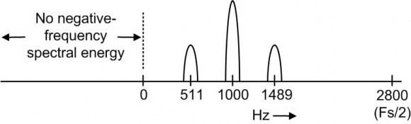
Hi Greg. I'm not able to understand the analog processing as you describe it in your 2nd paragraph. Can you tell me, if your original input analog carrier signal is amplitude modulated with a 489 Hz sine wave, does the following diagram roughly describe the spectrum of the digital (discrete samples) quadrature (I/Q) sequence produced at the output of your two A/D converters?
Also, if you collect 60 msec of samples at a sample rate of 5600 samples/second then you're collecting 336 samples. Is the 'N' in your Goertzel filtering equal to 336?
Rick,
You've got it exactly.
The reason I used Goertzel filtering is that I can use a custom 'N' for each frequency. Since the tone frequencies I'm interested in were chosen in an apparently random fashion, most of them do not fall directly on a frequency sample no matter what 'N' I choose. Using the Goertzel algorithm allows me to optimize the frequency domain sampling for each desired tone. My 'N' values range from 322 to 336.

I get a lot of flak for being an anti-fan of the Goertzel (it's fine for teeny processors, but if you can spend some clock ticks in the interest of clarity, ...)
The two versions of the Goertzel that I know of either give you anbut if a multiply is no more than twice or three times as slow as an add -- there's better ways). answer that depends on the phase of the incoming signal (i.e., give it \(\sin 2 \pi f t\) and it'll give you a markedly different answer than if you give it \(\cos 2 \pi f t\) ). The other version does some computation with the two state variables and basically coughs up an in-phase and quadrature result, which you can square and add for a "power level".
Are you using the right version of the Goertzel? Are you interpreting the results right?
If you can, it may be profitable to capture a stream of data points as they go into your detection algorithm, toss them into Scilab or Matlab to look at the spectrum. An FFT of the signal should show peaks at the note frequencies -- if there's no discernable bumps in a 336-point sample, then there's little hope of detection.
Tim,
Just out of curiosity I tried modifying the phase (0, 45, 90, 135, 180) of the incoming sine wave signal and there was very little difference between the Goertzel magnitudes that I measured at that frequency. It seems that the implementation I got a hold of doesn't have that problem.
Greg
So Greg, looking at the spectral drawing I posted on Jan. 24th, is your goal to detect the presence of the 511 Hz (or the 1489 Hz) tone? Stated in different words, is your goal to detect the presence of one of the sideband tones of the 1000 Hz tone?
Rick,
The end goal is to determine the modulated tones. So, you are correct that the sideband of the 1000 Hz carrier is what's important to me.
Currently, I demodulate the AM signal (your spectral drawing) by calculating the magnitude of each I/Q sample.
I then use the Goertzel algorithm to detect the 10 tones that I'm looking for. I've determined a fixed threshold to distinguish actual tones from noise.
Greg
https://www.dsprelated.com/showarticle/938.php
to perform AM demodulation?
If I understand you problem correctly here's what I suggest:
AM demodulation Method:
[1] Apply your original real-valued (I) analog signal produced at the output of your analog "cosine" mixer (a 1000 Hz tone AM modulated by some unknown-frequency sine wave) to a single A/D converter and perform AM demodulation on the converter's output sequence.
[2] You perform that AM demodulation using one of the "envelope detection" schemes described at:
https://www.dsprelated.com/showarticle/938.php
The 'fc' frequency in the figures of the above web page, in your case, will be 1000 Hz.
Next, your job is to detect the frequency of that demodulated sine wave
[3] Apply the output of the highpass filter to a bank of 10 Goertzel filters whose resonant frequencies are equal to 10 different possible frequencies of your expected demodulated sine wave. The resonant frequency of the Goertzel filter with the highest output magnitude will indicate what is the frequency of your modulating sine wave.
When I say "Goertzel filter" I mean the network shown in Figure 3 at:
https://www.dsprelated.com/showarticle/495.php
In that figure 3, 'N' is in your range from 322 to 336, and the 'k' variable is determined by the desired resonant frequency of the network relative to your Fs = 5600 sample rate.
I suggest using a Goertzel filter because it is a "matched filter" relative to an input sinusoid. That is, regarding a Goertzel filter whose resonant frequency is Fo Hz, the filter's impulse response is a complex sinusoid whose frequency is Fo Hz. And as far as I know a matched filter are the statistically optimum filter for maximizing your "probability of detection" of an Fo-frequency input sine wave.
Non-AM demodulation Method:
Thinking more about this, perhaps there's a way to perform tone detection on the upper sideband tone only, and eliminate the AM demodulation process altogether. Let me think more about that.
"Non-AM demodulation Method:
Thinking more about this, perhaps there's a way to perform tone detection on the upper sideband tone only, and eliminate the AM demodulation process altogether. Let me think more about that."
If he can be sure that the carrier isn't going to drift (i.e., that today he has a 1000Hz carrier, and tomorrow it's 900Hz), then all he should have to do is run a filter at the upper or lower sideband.
If the carrier moves around then that would have to be taken into account -- and performing an AM demodulation is certainly a conceptually easy way, and may be the best way.
SNR = 10dB with respect to what bandwidth? The bandwidth after running through the Goertzel filter (i.e., about 1/T), or the total bandwidth of your signal?
Tim,
I'm measuring 10 dB SNR over the air with a spectrum analyzer. The RBW is 500 Hz.
Maybe I can convince you of one of the benefits of the Goertzel algorithm. Apart from computational considerations, which I'm not too concerned with, when I tried using an FFT with these data several of my tones fell between frequency domain samples and appeared as broader peaks with lower magnitudes. Using the Goertzel algorithm I can adjust the number of samples for each of my desired tone frequencies so that they all fall directly on a frequency domain sample and my thresholding is much more effective.
The algorithm I'm using works with real data only. Do you think a quadrature result would give me more signal vs the noise? That could be a solution to my problem.
Thanks,
Greg
Your filter length is 60ms (give or take a few samples). The Goertzel algorithm implements a boxcar-in-time filter (which translates into a sinc function centered around the Goertzel's center frequency, in the frequency domain). It's bandwidth is 1/60ms = 16.7Hz (if I'm getting my math right -- do check if I've misplaced a decimal point).
So if you're measuring the SNR at 500Hz, you should be seeing a SNR improvement of \(10 \log_{10} ((500)(0.06))\) dB, or around 15dB. At your 0dB measured SNR, your signal should still be 15dB above the noise -- which should be loud and clear.
The action of the basic Goertzel is to give the same result as multiplying the incoming signal point-by-point to a sine wave at the Goertzel frequency and adding the result to an accumulator. This means that phase matters -- if you happen to sample your Goertzel at a trough, you'll get no signal.
There is a way, which I cannot remember (I'd have to sit down with a pencil and paper and do math), to look at both states of a Goertzel and extract the quadrature result, without having to actually run a separate filter. Hopefully someone will chime in with the answer -- if they don't, you may want to start a new thread asking just that question.
(Edit: I'm pretty sure I'm off by a factor of two on the effective bandwidth, and in the wrong direction. So the total bandwidth is 33Hz -- which still leaves you with a 12dB processing gain.)
"when I tried using an FFT with these data several of my tones fell between frequency domain samples and appeared as broader peaks with lower magnitudes."
Well, yes, but I wasn't suggesting you do an FFT -- there's more tools in the DSP toolkit than the Goertzel and the FFT. In particular, you could do the multiply-by-sine-and-add that I mentioned as the equivalent of the Goertzel. That would be my first go-to if I wasn't trying to squeeze the processor for clock ticks. On the one hand it is most certainly more processor intensive, but on the other hand it is (in my opinion) more readable and maintainable, with fewer pitfalls for the unwary.
(And note -- if you had to do this on an 8051 or a PIC -- use the Goertzel!).
Tim,
I'm not married to the Goertzel algorithm. It just seemed like the best alternative for tone detection in my case.
Would you point me to detailed descriptions of alternative tone detection methods? I'm using a processor that's powerful enough to do a lot more calculating than I am currently doing.
You are asking the guy with the worst Google-fu in the universe for keywords. Just so you know.
"Matched filter to a pulsed tone" is probably close, but may not get you any hits.
If you can stand complex notation:
\[y = \sum_{k=0}^N {x_{n-k} e^{j \theta k}}\]
where \(\theta = \frac{f T_s}{N}\), \(f\) is your center frequency, \(T_s\) is your sample time (i.e., 1ms if you're sampling at 1kHz), and N is the number of samples you want to take. The magnitude of \(y\) is your answer.
If you choose \(\theta\) and \(N\) so that the complex exponential rotates through an integer number of cycles, then this is a one-point DFT. Chosen in that manner, the imaginary part will be exactly equivalent to what the Goertzel would spit out, while the real part contains the rest of the story.


