


Adding 45 degrees phase shift to a FIR bandpass
I feel rather uneasy to use a 90 degree Hilbert transformation on one channel while the other ist only delayed. A much better idea would be, to shift one signal for +45 degrees and the other for -45 degrees, using just one set of taps for the FIR filter. For one signal applying the taps from 1 upto numtaps and for the other from numtaps downto 1.
I came to this forum by reading a paper "An Efficient Analytic Signal Generator" from Clay S. Turner.
He discusses a rather different situation, but the frequency shift he used there, was very interesting to me. I simulated his formula (9) and on the very first glance it works nicely, but in the second view it is not suitable for a receiver's bandpass filter. His calculations are simply for a quite different purpose.
My procedure is:
- make a lowpass for the lower frequency edge, normalize it.
- make a second lowpass for the upper frequency edge, normalize it.
- turn the second lowpass into a highpass by spectral inversion
- add the two passes to get a bandreject
- turn it into a bandpass (or not, depending on what I want to see on simulation)
I do know the ready made software from iowa hills. It can be used to calculate nice filter kernels, but exactly THIS is not my intention. In the end I need the procedure in a suitable programming language to implement it into a microcontroller. So the operator can change the bandwidth or shift the passband while hearing the transmission. Also he can adjust possible phase errors of the analog I/Q-Mixer by adjusting the digital phase shift (I imagine a range of +/- 2 degree around 45 degrees is enough)
So, my questions are:
How to apply a adjustable phase shift in the range of 43 to 47 degrees on the taps of a FIR filter?
Can it be appiled after the bandpass itself is calculated or needs it to change the bandpass calculation itself?
Is there one, who can help such a old one like me?
kind regards
wolf22

So, I'm going to disagree with everyone else and say that yes, if you see the value in it, go ahead and proceed with your plan.
Since you're making the filter anyway, just make your desired response in the frequency domain, with the appropriate phase shift, and do an IFFT to get the filter kernel. You already know that you'll want one filter with a +45 degree phase shift and one with a -45 degree shift.
Personally, I'd try it both ways: one with the filters as described above, and one that has a 90-degree shift bandpass and a no-shift bandpass.
I _do_ believe that if you're bandpass filtering anyway, you may as well do the phase shifting in the bandpass filters -- it makes more sense to me than a separate all-pass filter.
Note that with the Hilbert in there, to get the desired shift at low frequencies you need a filter length that's more or less proportional to the sampling rate divided by the lowest frequency you want it to work at. I don't know what the constant of proportionality will be, but if you're doing high-fidelity expect much longer filters than if you're doing communications work.
Of course it is essential to do the phase shift together with the filtering in the same filter kernel. I must not waste any computing power by running two kernels, where one kernel can do the job - just only with suitable calculated taps.
Today's Cortex M4F CPU's run in most cases with ca. 100 MHz, so if I have the I/Q stream with usual 96 kHz sample frequency, I only have ca. 1000 clocks for both channels.
kind regards
wolf22

What you want is an "all pass filter". It can shift specific frequencies by a specific phase. Here's the first web hit I found: http://www.edn.com/electronics-blogs/living-analog... Adjusting digital coefficients is the same as adjusting resistors in an analog circuit.
You can put it into the band pass filter, but it is probably easier to make it separate since you want control over the phase without changing the bandpass requirements.
Sounds like a fun project, good luck with it!
Dr. mike
Wolf,
In a digital implementation, there is no reason to avoid putting all the phase shift into one of the channels. (Back when we did this with analog circuits, we constructed a pair of channels whose phase difference is 90 degrees, allowing their actual phases to vary widely.) The Hilbert transformer should have an odd number of taps so that its delay is an integer number of clock pulses. As for the delay in the unshifted channel, simply take the value at the HT's middle tap.
Jerry
To my understanding, as an RF engineer, digital filter is weighting the magnitude of time signal. On the other hand, a phase shifter is basically a time delay. In analog domain, it could be lumped L or C, and transmission line as distributed element. It depends on operating frequency and/or wavelength.
Best regards,
Shahram
Oh, I think, I am a little misunderstood. Some years ago I tried the whole thing in analog hardware, but the time to do so, seems to be over. So I began to think on software solutions
The picture below (I hope it is visible) shows the middle of a bunch of 201 taps bandpasses, which will pass from 100 Hz to 2.7 kHz (usual SSB range), has ca. 80 dB damping in the stopband and it turns the phase of ALL frequencies in this range by the amount visible in the right upper corner. The frequency filtering behavior is the same for all the shown filters.
Those taps are the result of a software from iowa hills and not calculated by me. I only simulated the filter kernels created by the iowa software.
It is really my intention, to implement the calculation procedure into a suitable microcontroller and make it customizeable by the operator.

from left to right: the tap num, from bottom to top: the value of the taps. I only displayed the middle of the whole filter kernels, because the outer areas are rather less interesting due to Blackman window.
kind regards
wolf22

Herr wolf,
I wonder if the material at:
www.faculty.ece.vt.edu/swe/argus/iqbal.pdf
would be of some use to you.
Tschuss,
[-Rick-]
Dear Richard,
thanks for the hint, but it does not really touch my problem. I have a rather strange impression regarding this topic: Today nobody constructs a rf receiver in the old analog way with quartz or magnetomechanical filters and so on. They all do it now in the SDR way. But obviously they all need to cancel out the unwanted images, so everybody needs to apply phase shifts somewhere in the digital signal path. But even extensive searching the internet does not give useful results. So I have just 2 conclusions in the moment: 1. I am too stupid (probably), 2. nobody wants to talk about it.
As you are a author of a rather large book I have seen on Amazon, I think, you have a lot of experience how things look like, if they are separated and displayed graphically. So I was curious to see the differences between filter kernels with decent phase shifts and the same filter kernel without any phase shift.
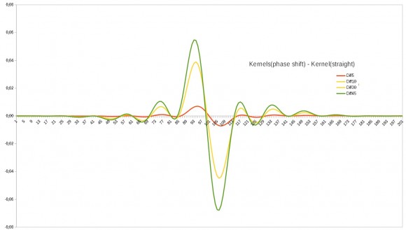
The picture above shows some differences of FIR band pass filters for 5, 30, 45 degrees phase shift:
Kernel(shift)-Kernel(no shift).
The kernels are from the iowa hill software. The 45 degree (green) does not look symmetrical and the values of the center tap are not zero for all displayed curves. The kernels themselves give a nice constant phase shift inside the passband. To me it looks like a cos(phi)-sin(phi) thing. Do you have a better idea?
kind regards
wolf22
I'm not sure that I can be of help because I'm not sure what you are trying to do. If I recall correctly, you want to perform single-sideband (SSB) demodulation.There are a number of methods to perform SSB demodulation and I don't knowwhich method you are trying to implement. It would help us, here on dsprelated.com, to help you if you would provide the block diagram of the processing you want to perform.
Having said that, you are now focusing on some sort of bandpass filters. You provided several colored squiggly curves that, I think, you call "kernels."The word "kernel" means different things to different people. By "kernel" do you mean "time-domain impulse response"?
wolf22, as you know, digital filters exhibit different amounts of frequency-domain phase shift at different frequencies. I don't know what is means to say "a FIR bandpass filter has a 5 degree phase shift." Can you explain what the words "has a 5 degree phase shift" mean?
You posted the line, "Kernel(shift)-Kernel(no shift)." Can you tell us what the terms "Kernel(shift)" and "Kernel(no shift)" mean? Is the hyphen, in "Kernel(shift)-Kernel(no shift)", really a hyphen or does it mean subtraction?
[By the way, the iowa hills software web site is certainly an interesting web site!]
Regards.
Oh, you ask for a more detailed description. So I will try:
1. Converting down a rf signal to baseband with a I/Q-mixer will give 2 signals in the baseband named I and Q, where one has a phase shift of 90 degrees to the other.
2. Both signals need to be decently lowpassed and then passed to a dual channel ADC with a known sample frequency (let me say for example 96 kHz). After this both signals are in the digital world.
3. Besides of some side-purposes like band scope and so on, both signals need to pass a suitable band pass to remove all content, which is outside the desired signal content. So we have after passing both signals through the band pass only the two items: the desired side band and the undesired side band, which is simply the part of the hf area, which is mirrored by the frequency of the a.m. mixer's oscillator's (the "LO") frequency.
Let me say: I have the LO on 139.100 MHz and therefore I receive the desired band 139.10009 MHz to 139.1027 MHz and together the unwanted band 139.09991 MHz to 139.0973 MHz. After downconverting I get the desired side band of 90 Hz to 2700 Hz and the undesired side band of -90 Hz to -2700 Hz, folded onto the desired side band.
4. To remove the unwanted side band, I need to shift all signals of the already phase shifted signal by another 90 degrees in phase. Then I can add both signals I and Q and in the end the unwanted side band cancels out. What is left, is my desired signal, ready to hear.
5. How to do the filtering? The filter I feel to be best suitable for this is a FIR filter. In principle it consists of a storage, where the last N samples are stored, then a storage, where N factors are stored and a simple algorithm: (I write it in a quasi Pascal notation, because this is best readable in my opinion)
N = Number_Of_Filter_Taps; // fore example 201 to have the uneven
// the storage for the last N samples:
Samples : array[0 to N-1]; //usually of type float or so
// the Kernel, this is the storage for the N taps:
Kernel : array[0 to N-1]; // also usually float or so
Q:= 0;
for i:= 0 to N-1 do
Q:= Q + Kernel[i]*Samples[i];
Filtered_Result:= Q;
The Array of factors is called the filter kernel (or in short the "kernel") and it's elements are the taps.
When you set all taps to 1.0, then you get a simple moving average filter. But there can be done a much better filter by designing the taps differently. In my first picture you see the middle of such a filter kernel with N=201. The whole thing is a band pass filter, which gives a passband from ca. 90 Hz to ca. 2700 Hz when the sample rate is 44.1 kHz. It is somewhat amazing, how steep and deep the edges of this filter are.
The symmetric curve in the picture ist the one, which gives a filter with zero phase shift for all frequencies in the output. They are only delayed by 100 samples. Yes, if we delay the input signal by 100 samples (from 1 to 101) and compare the output of the filter to this delayed input samples, we find, that the phase is EXACTLY zero for all passed frequencies. Yes, for ALL.
All the other curves, which are slightly non-symmetric, give the same filter characteristics, but apply a constant phase shift to ALL frequencies inside the passband. This is just more amazing. We have a nice band pass AND a phase shifting item with only ONE kernel (array of taps)
In my second picture I displayed a result of my curiosity: I simply subtracted from all taps of a phase shifting kernel the according tap of the non-phase shifting kernel to see, what the difference is. This is displayed in the picture. Symbolic:
Result : array[0 to N-1];
for i:= 0 to N-1 do
Result:= Kernel_with_phaseshift[i] - Kernel_without_phaseshift[i];
So. I hope to be understood a little better. But writing so much in english, I doubt to have expressed myself always as I thougth so. (my problem is, that I never had any education in english language...)
kind regards
wolf22
p.s.: my name is 'realiter' Wolfgang, but exactly THIS has been occupied by someone other, so I needed to change the nick to somewhat accepted by this web site and also memorizeable by me.
Dear Wolfgang,
Your English grammar is VERY good!
I do not understand everything you wrote in your last reply. I have too many questions to ask of you and I do not want to make you become frustrated with all my questions. But I will say the following:
[1] To avoid confusion, in the future, when you communicate with other people about FIR filters, I suggest that you do not use the word "kernel." Instead of referring to an FIR filter's "kernel", refer to an FIR filter's "coefficients."That way, everyone will know exactly what you mean with no confusion.
[2] You wrote that you have an FIR filter that has zero phase shift at all frequencies. I do not believe such an FIR filter can exist for real-time signal processing. Your 201-coefficient FIR filter will have a time delay of 100 samples (if the coefficient values are symmetrical) but it will not have a zero phase at all frequencies.Wolfgang, apply a single sine wave sequence to your FIR filter and compare the phase of the filter's output sine wave sequence to the phase of the input sine wave sequence. The output phase will be different from the input phase (the difference between the two phases will not be zero).
It would be interesting to me if you posted the 201 coefficient values of your "zero phase shift" filter in your next reply here.I'd like to compute the frequency-domain magnitude and phase responses of that fiter.
[3] You wrote that the output of your two ADCs were an I sequence and a Q sequence down-converted to baseband.To me, that means you have a signal of interest that is a complex valued sequence 'I + jQ' that is centered at zero Hz.Such a signal is called a "lowpass' signal because it only has spectral energy in the vicinity of zero Hz.But then you write about performing bandpass filtering of your lowpass signal, and that confuses me.
[4] I'm not at all sure I can be of help to you. But, based on my Figure 13 at:
https://www.dsprelated.com/showarticle/176.php
I suggest you consider the single-sideband (SSB) demodulation method shown below:

In that hypothetical scenario, the cutoff frequency of the FIR LPFs (lowpass filters) is just a bit greater than 2 kHz. I believe you should be able to achieve acceptable lowpass filtering with fewer than 201 FIR filter coefficients. In my figure I suggested decimating the filters' output sequences because that will reduce the number of overall arithmetic computations that you must perform.
If the Hilbert transformer (HT) has an odd number of coefficients then almost half of those coefficients will be zero-valued.This makes odd-length HTs computationally efficient (fewer computations per input sample). Also, I suggest you use what's called the "folded block diagram" implementation for the LPFs and the HT in order to further reduce the number of arithmetic computations that you must perform.
Dear Richard,
your picture shows nearly my ideas. But the part of the signal way you have named "decimation", is in my imagination quite different: It consists of 2 FIR filters (one for I the other for Q), which not only apply a band pass to the signals, but also apply a +45 degree phase shift to the one and a -45 degree phase shift to the other. So the following delay and hilbert are simply unnecessary. The only point is, to apply the necessary phase shift to the "FIR bandpass filter coefficients" (the "Kernel"...).
Yes, it's really possible to do so. I try to append here the little documentation for my self written PC software: Filterbastler.pdf I hope, this works. Also I try to append some coefficients here: Filters_from_IOWA.zip hoping this works..
But be aware, that my PDF is in german. I wrote it last fall - more or less just for me. Just remember, any phase measurements need to be done between the output of the filter and the input samples delayed 1/2 of the whole filter length. Therefore the length should be odd. If you are interested, I can send you the sources. I used the old but nice Delphi6, but it should also be possible to use the sources with Lazarus/Freepascal.
kind regards
wolf22
Rick,
This thread is ancient, but I'd like to revisit it:
One thing that has prevented me from implementing a SSB demodulator as above is the usable lower frequency response of the Hilbert. (or more precisely the lack thereof)
I wouldn't presume to interpret wolf22's original question, but I wonder if he was asking how to implement a FIR filter with an across-the-board 45-degree phase shift. If one had such an animal, you could put a -45 degree shift in one channel, and a +45 degree shift in the other, assuming I have my avians aligned. His reference to the Iowa Hills "phase adjusted" bandpass code is what led me to consider this.
In any case, a set of matched LPF's to set the audio response that just happened to have + and - 45 degree shifts across the bandpass would seem to be a good thing to have, but unfortunately outside of my wheelhouse. Bob Larkin had a design years ago that implied he could generate those, but I haven't seen any reference since.
Thanks,
--jim
Hello again,
I digged out this old topic, because I think, that the final solution may be of interest to people, who are interested in SDR projects.
So let's start with a kind of recipe:
first some prerequisites:
a) consider to build a filter kernel with a ODD number of taps, because there we have exactly one tap in the middle of the filter. This is important.
So let us assume, the indices run from -N to +N, making a total length of 2N+1 Taps.
b) consider, that all frequencies are expressed as a part of the sample frequency and by the value, which is named "kreisfrequenz" (in german).
So let us assume F = 2 * Pi * (F_desired / F_sample)
c) consider, that the known and widely used filter function, which is also used here, is the sin(x)/x function. This function makes a filter kernel, which is mirror-symmetric to it's middle.
This is Tap[i] = Tap[-i]
You will need to build a bandpass with this function.
But you also need to build a second bandpass with it's hilbert transformated: this is simply the (1 - cos(x))/x function. This makes a filter kernel, which is point-symmetric to it's middle.
This is Tap[i] = -Tap[-i]
d) a lowpass filter kernel is simply built in the following way, using two arrays P_re[-N..+N] and P_im[-N..+N]
given: F // this is the cutoff frequency
for i:= -N to +N do
begin
if i = 0
then
begin
P_re[i]:= F;
P_im[i]:= 0;
end
else
begin
P_re[i]:= sin(F * i) / i;
P_im[i]:= (1 - cos(F * i)) / i;
end;
end;
After calculating all of the taps, both filters need to be windowed, I prefer the Kaiser window, but you can also use another window (Blackman etc.) and after this both filters need to normalized. There is a catch normalizing the P_im due to it's been point-symmetric. Simply use the sum you got for the P_re.
e) you need to build a bandpass, because on two frequencies the signals cannot turned in angle: zero and Fsample/2. So the bandpass is the only remaining characteristic you can successfully calculate.
f) consider how to turn a lowpass into a highpass: simply toggle the sign of every tap (Tap[i]:= -Tap[i]) and then add 1.0 to the Tap in the middle (Tap[0]:= Tap[0]+1.0)
now comes the recipe:
1. calculate a lowpass filter for the upper cutoff frequency
2. turn this lowpass into a highpass
3. calculate a lowpass filter for the lower cutoff frequency
4. add both filters tap by tap, this makes a bandstop
5. turn the bandstop into a bandpass according to prerequisite f)
Keep in mind, that you need to do it with both kernels P_re and P_im in every step.
Now you have 2 semi-final filter kernels: P_re and P_im, one is a bandpass with phase shift of zero and the other is a bandpass with phase shift of 90 degrees.
To get a final bandpass with the desired phase shift, you need to turn every pair of taps according th the usual method, which is also used in the CORDIC algorithm. But you need only the half:
given: phi // the phase shift (usually from -PI/2 to +PI/2)
for i:= -N to +N do
begin
X:= P_re[i];
Y:= P_im[i];
FinalKernel[i]:= X * cos(phi) - Y * sin(phi);
// unused[i]:= X * sin(phi) + Y * cos(phi);
end;
That's it. You got the final filter kernel, which is a bandpass with a phase shift of your desire.
kind regards
wolf22
Hi wolf22,
I am working on a project similar to what you describe and would be interested to see your code you offered. The pdf looks intriguing and has spurred me to further progress the project.
I realize this is an old thread but hope prevails.
beaka


